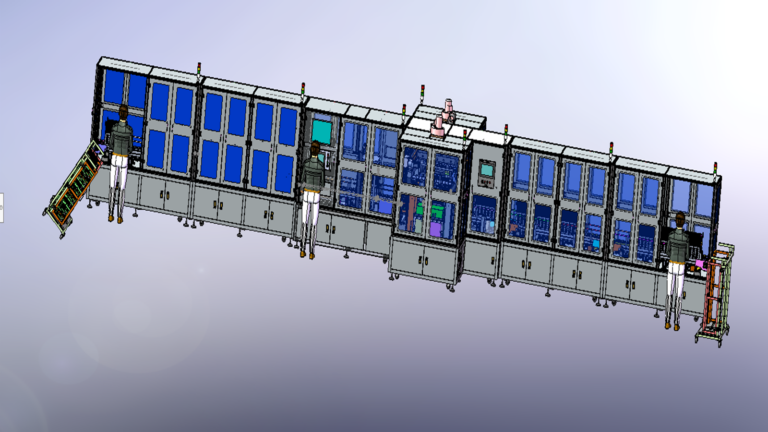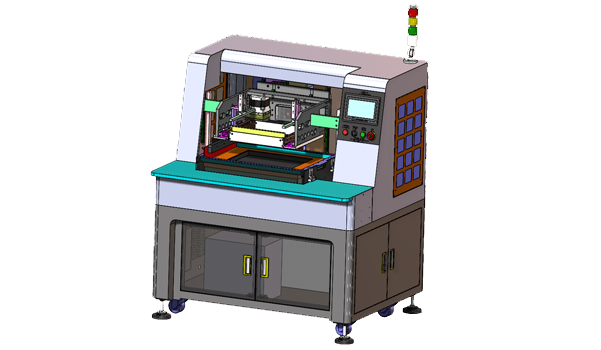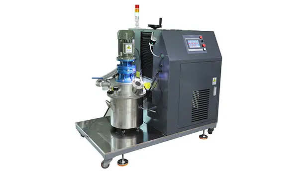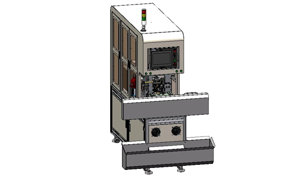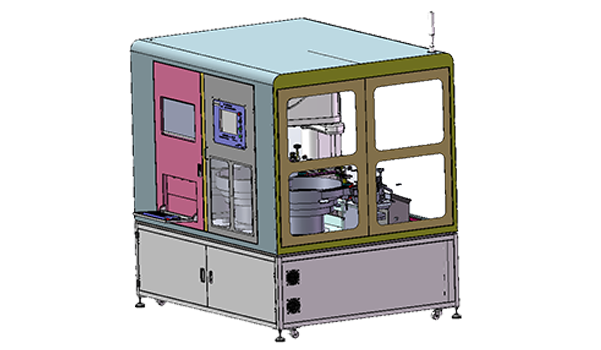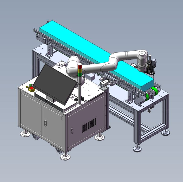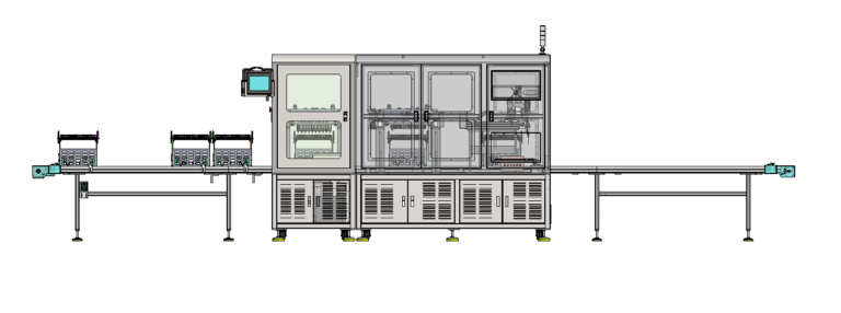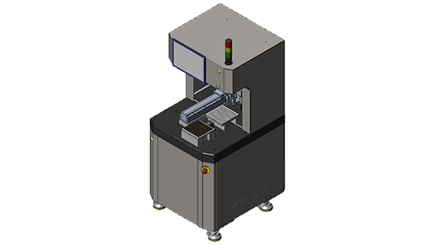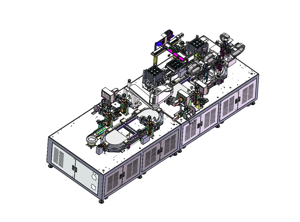
In AC/DC charging socket manufacturing, a Bushing Automatic Assembly Line often needs to handle product variants that share most of the same structure but differ in a small number of components. This AC/DC Socket Bushing Automatic Assembly Line case supports both AC and DC charging-socket bushing variants. The two products share the main processes for Thermistor handling, Plastic Housing feeding, Assembly, Laser Welding, Resistance Testing, CCD Inspection, and Tray Handling. The DC version adds one extra Resistor, so the front end includes an additional Resistor Feeding and Transfer step. The line is planned for an average output of 300–350 products/hour.
That difference shapes the line architecture. The project does not split AC and DC into two completely independent production lines, nor does it try to absorb every difference through a PLC Recipe. The Resistor process that belongs only to the DC version is kept in a clearly defined module, while the remaining operations continue along the same shared assembly, welding, and testing route.
Robotlyne’s Electronics Assembly Automation covers multi-process automated assembly, automated loading and unloading, Testing, and Inspection, making it relevant to projects that combine small-component feeding, assembly, welding, and inspection on one production line.
One Extra Resistor Is the Main Difference Between AC and DC
In this project, most of the process remains the same for the AC and DC versions.
Both require Thermistor handling.
Both require Plastic Housing.
Both continue through Assembly, Laser Welding, Resistance Test, CCD Inspection, and Tray Loading.
The additional process appears only in the DC version:
DC = Shared AC/DC Route + Resistor Feeding / Transfer
The AC route does not require this step.
This means the line’s flexibility starts with a concrete engineering question rather than the abstract goal of “supporting both AC and DC variants”:
At which process step do the two products actually become mechanically different?
In this case, the answer is the Resistor.
The DC version therefore adds dedicated Resistor Feeding and Handling, while the AC version bypasses that section. After the variant-specific work is complete, both versions return to the shared route.
This avoids duplicating a large amount of equipment. If AC and DC were built on separate dedicated lines, Thermistor Feeding, Housing Feeding, Assembly, Laser Welding, Testing, and Tray Handling would all need to be duplicated.
At the same time, the project is not designed as a universal machine.
The case defines it as a dedicated-purpose machine. If the assembly product changes substantially, the Fixtures and Grippers need to be replaced, and Incoming Material Dimensions must remain within the corresponding Tolerance Range.
The compatibility boundary is therefore clear.
The equipment can share a large portion of the process across the planned AC and DC variants. But if the product geometry moves beyond the existing Fixture and Gripper conditions, a software Recipe cannot replace the required mechanical changeover.
Variant compatibility does not mean universal flexibility.
The Shared Route Starts After the Variant-Specific Front-End Work
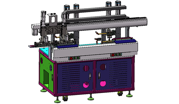
The case uses front and rear 8-station ring-type magnetic levitation loops.
Rather than treating the two loops as separate equipment modules, it is more useful to follow how the product moves from variant-specific component preparation into the shared assembly route.
At the front end, different components are prepared separately.
The taped Thermistor passes through the Reel Shaft, Stepping Cut-and-Feed, Lead Cutting, left/right Forming Pushers, Front Pusher, and PPU Feeding before a Four-Axis Pickup and Transfer Mechanism moves it forward.
The Plastic Housing is fed through a Vibratory Bowl, Straight Vibration Rail, and Separation Module, then picked with a dedicated Suction Nozzle.
If the current product is the DC version, the Resistor also goes through its own Feeding and Transfer process.
Only after these front-end preparation steps are complete are the required components brought into the downstream shared assembly area.
From there, the process begins to converge again.
A Four-Axis Assembly Robot uses a Shaped Assembly Suction Nozzle and Pressure Sensor to complete assembly.
The product then enters Solder-Paste Dispensing, where the equipment uses a three-axis module, Dispensing Needle, and Laser Height Sensor.
Next come two three-axis Laser Welding Modules.
After welding, the process continues through Cooling, Resistance Testing, CCD Weld Appearance Inspection, and final Tray Handling.
The route can be simplified as:
Variant-Specific Feeding → Shared Assembly → Dispensing → Laser Welding → Resistance Testing → CCD Inspection → Tray Loading
Seen this way, there is no need to speculate about why the project had to use two loops. The case does not publish a comparison between a single-loop and dual-loop design, so it would not be accurate to assign a specific reason such as takt balancing or commissioning convenience.
What the confirmed layout does show is a relatively clear mechanical separation between front-end component preparation and the downstream assembly, welding, and testing area.
Across these areas, the product still depends on the Fixture Table, Moving Platform, and Secondary Positioning Structure to maintain a stable positional relationship.
This matters with small electronic components.
The Thermistor, Housing, and Resistor come from different Feeding Mechanisms, but they ultimately need to arrive at Assembly and Welding in the correct relative geometry.
Every additional variant-specific component at the front end becomes another assembly condition that must remain stable downstream.
300–350 Products/Hour Is a Line-Level Result
The case gives an average line output of:
300–350 products/hour
The Laser Welding validation note also provides three specific figures:
3 seconds per single weld point
6 weld points
2 three-axis laser welding systems
These figures help describe the welding process, but they are not enough to calculate the total line takt directly.
A simple calculation of 3 s × 6 weld points = 18 s still leaves several unknowns.
The case does not explain how the two Laser Systems divide the six weld points.
It does not confirm whether the two systems operate fully in parallel.
It also does not publish how the product transfers between the two Welding Stages.
And Welding is only one part of the line.
Before the Laser Station, the product still passes through Solder-Paste Dispensing and Laser Height Measurement.
After welding, it continues through Cooling, Resistance Testing, and CCD Inspection.
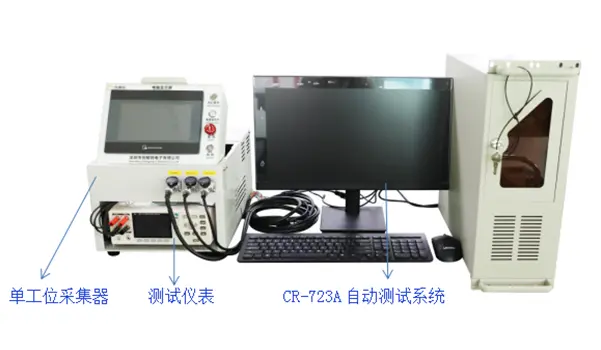
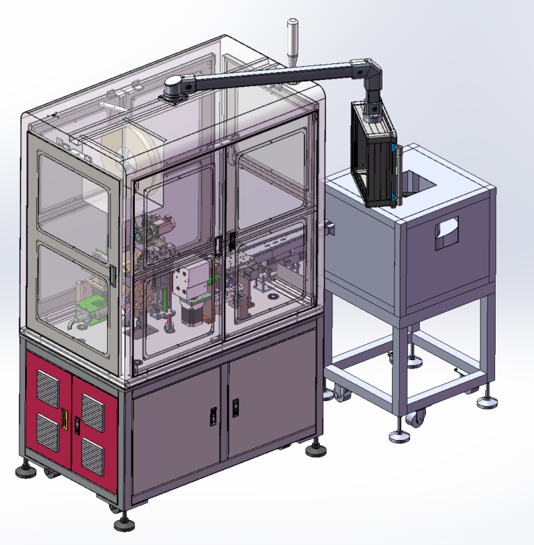
The final products then enter a Nonstop Tray Loading / Unloading system with a Waiting Tray Warehouse, Finished Tray Warehouse, Working Bay, and Lifting Component.
NG products are handled separately by a Four-Axis Pickup and NG Rejection Module.
For this reason, 300–350 products/hour is better treated as the average capacity of the complete Bushing Automatic Assembly Line.
One particularly relevant detail is the Tray Handling design.
The project does not follow a stop-and-change sequence in which a full tray forces the main production process to stop for manual replacement.
Instead, Nonstop Tray Loading / Unloading uses the Waiting Tray Warehouse, Finished Tray Warehouse, and Working Bay to manage tray changeover.
Maintaining 300–350 products/hour therefore depends on more than the assembly and welding equipment themselves.
Front-end component feeding, the DC Resistor Module, Assembly, Dispensing, Welding, Testing, CCD Inspection, and Tray Logistics all need to remain sufficiently synchronized.
The case does not publish the individual Cycle Time of each station, so there is no reason to create an unsupported theoretical Line Balance.
What the available information does confirm is that the AC and DC differences are confined to a defined front-end module, while both products later share the main Assembly, Welding, Testing, and Tray Handling route and reach an average line capacity of 300–350 products/hour.
This is the clearest engineering conclusion from the project.
For a new AC/DC charging socket product family, if the variants differ only in certain Components or Assembly Steps, the first question should not be how many production lines to build. It should be which processes can be shared and which differences require their own mechanical modules.
Once that boundary is clear, Fixture design, Transfer, Welding, Testing, and Tray Handling can be planned as one line architecture. If the AC/DC variant differences need to be converted into a specific equipment concept, contact Robotlyne to discuss how the shared route should be divided.