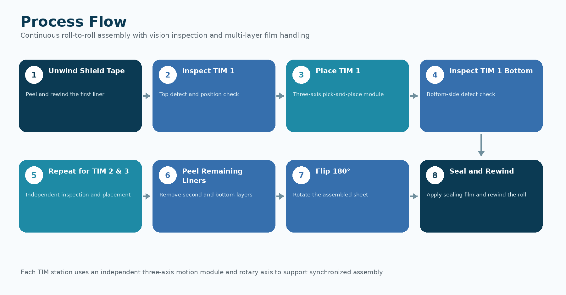
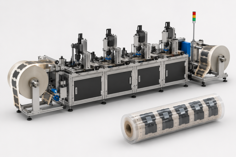
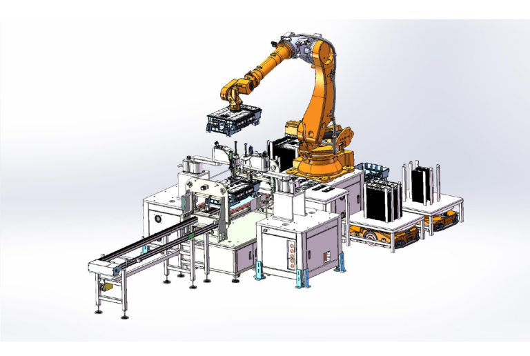
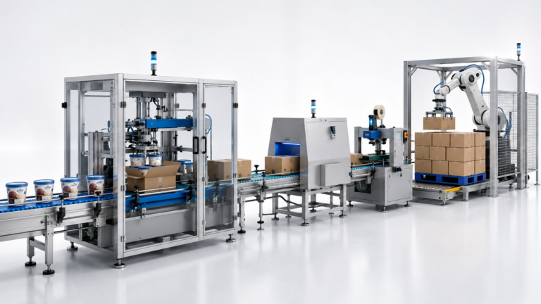
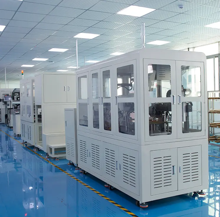
The project objective was to automate the assembly of three small TIM rubber components onto a shield-tape substrate and package the completed material as a finished roll. The shield tape, TIM Rubber 1, TIM Rubber 2, TIM Rubber 3, and sealing material were all planned as roll-fed inputs arranged in a 1 × 1 single line.
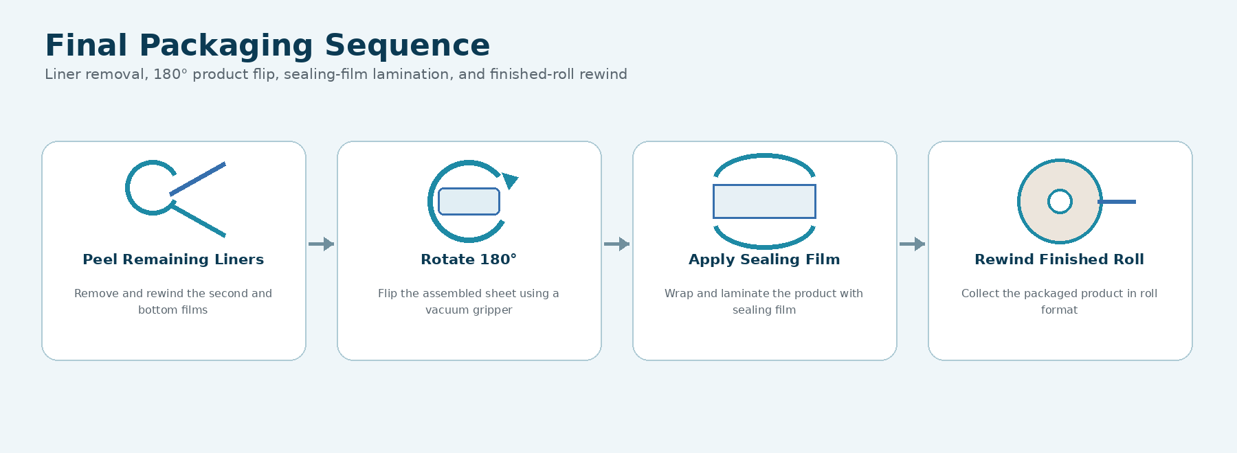
The line needed to inspect each rubber component for top-surface defects and position, verify bottom-side defects, confirm the substrate position, remove multiple protective films, rotate the assembled sheet by 180 degrees, apply sealing film, and rewind the packaged product.
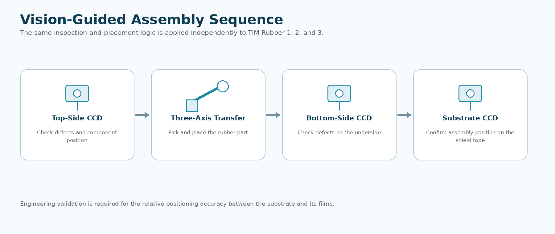
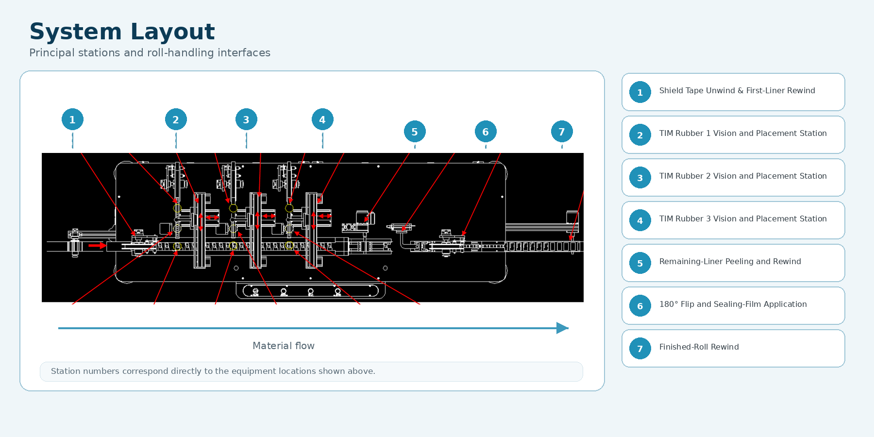
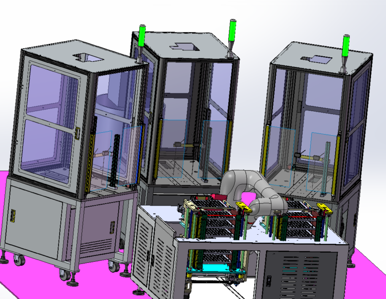
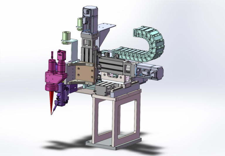
The proposed solution uses the shield tape as the main continuous web. Its first protective layer is peeled and rewound before the web enters three independent assembly stations. Each station combines CCD inspection, a three-axis pick-and-place module, and an independently controlled rotary axis for one TIM rubber component.
At each station, the upper surface and position of the rubber component are inspected, the component is transferred to the main line, the underside is inspected, and the substrate position is checked before assembly. After all three rubber parts are assembled, the remaining liner layers are removed, the sheet is flipped 180 degrees, sealing film is applied, and the finished product is rewound.
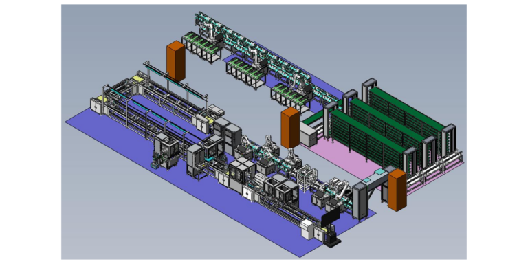
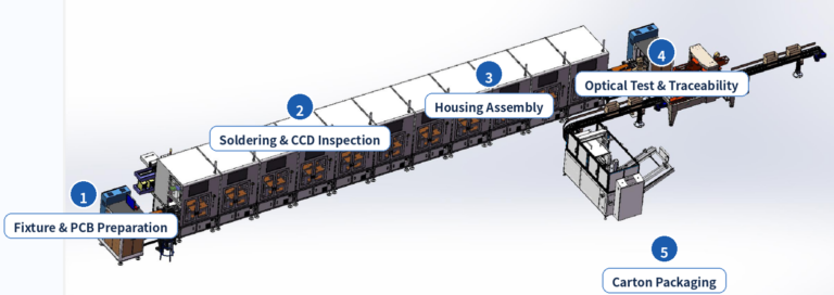
The system is designed as a continuous sequence from shield-tape unwinding to finished-roll collection. Three separate rubber assembly stations repeat the same vision-inspection and transfer logic, followed by film removal, product flipping, sealing, and rewinding.
The following equipment functions are derived directly from the supplied project layout and process descriptions.
| No. | Equipment Name | Quantity |
|---|---|---|
| 1 | Varistor Feeding and Lead Forming Machine | 1 Set |
| 2 | Automatic PCB Feeding Machine | 1 Set |
| 3 | Cartesian Soldering Machine | 3 Sets |
| 4 | Upper Housing Automatic Feeding Machine | 1 Set |
| 5 | Lower Housing Automatic Feeding Machine | 1 Set |
| 6 | Base Cover Automatic Feeding Machine | 1 Set |
| 7 | Labyrinth Automatic Feeding Machine | 1 Set |
| 8 | Lead Cutting and Forming Machine | 3 Sets |
| 9 | Barcode Scanner | 36 Sets |
| 10 | Contact Displacement Sensor | 10 Sets |
| 11 | CCD Vision System | 8 Sets |
| 12 | Industrial Robot | 16 Sets |
The equipment values below are the design parameters stated in the supplied proposal. They should not be presented as final acceptance results unless confirmed by project test records.
| Specification | Details |
|---|---|
| Equipment Size | 16000 × 2600 × 1800 mm (L × W × H), subject to final design. |
| Incoming Product | Injection molded parts |
| Working Efficiency | 600 to 700 PCS/H |
| Drive Method | Servo motors, screw rods, and robotic handling |
| Positioning Accuracy | ±0.02 mm |
| Motion Guide | Imported silver rail guides and screw rods |
| Control System | PLC and touchscreen control system |
| Programming Method | PLC |
| Power Supply | 380VAC, 50HZ |
| Air Pressure | 0.5 MPa |
| Machine Weight | To be confirmed |
| Communication Port | USB and Ethernet |
The proposal also defines roll and liner requirements for the rubber materials. These requirements are important for stable unwinding, die-cut transfer, and continuous assembly.
Planning a Vision-Guided Assembly and Roll-Packaging System?
Contact Robotlyne to evaluate your material structure, roll specifications, inspection requirements, cycle time, equipment scope, and ROI.
Got questions? Ideas? Fill out the form below & our specialist will contact you.
Got questions? Ideas? Fill out the form below & our specialist will contact you.