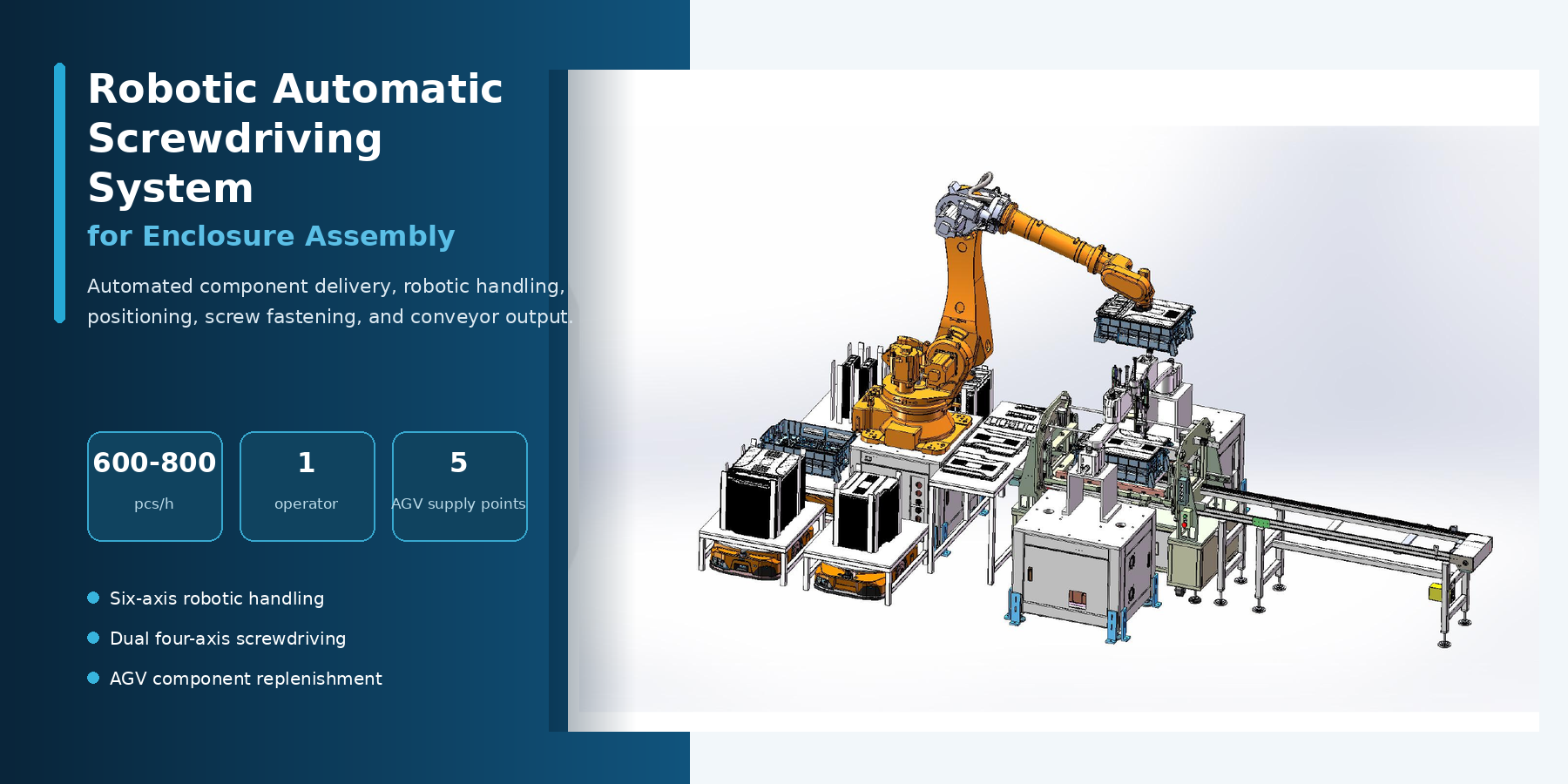
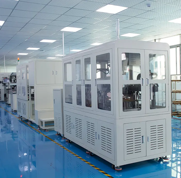
The project required an automated cell for fastening the lower cover, upper cover, upper sealing plate, and side sealing plate to an enclosure body. The line needed to coordinate component supply, robotic handling, enclosure positioning, screw fastening, and finished-part transfer.
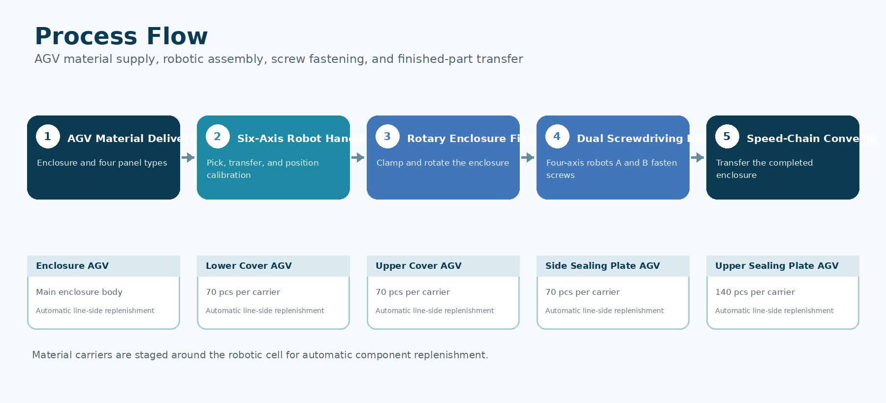
AGVs were planned to deliver the enclosure and the four component types to dedicated staging positions around the robotic cell. The supplied design specifies 70 pieces per carrier for the lower cover, upper cover, and side sealing plate, and 140 pieces per carrier for the upper sealing plate.
The specified target was a design throughput of 600-800 pieces per hour with one planned operator, supported by PLC, touchscreen, and industrial-computer control.
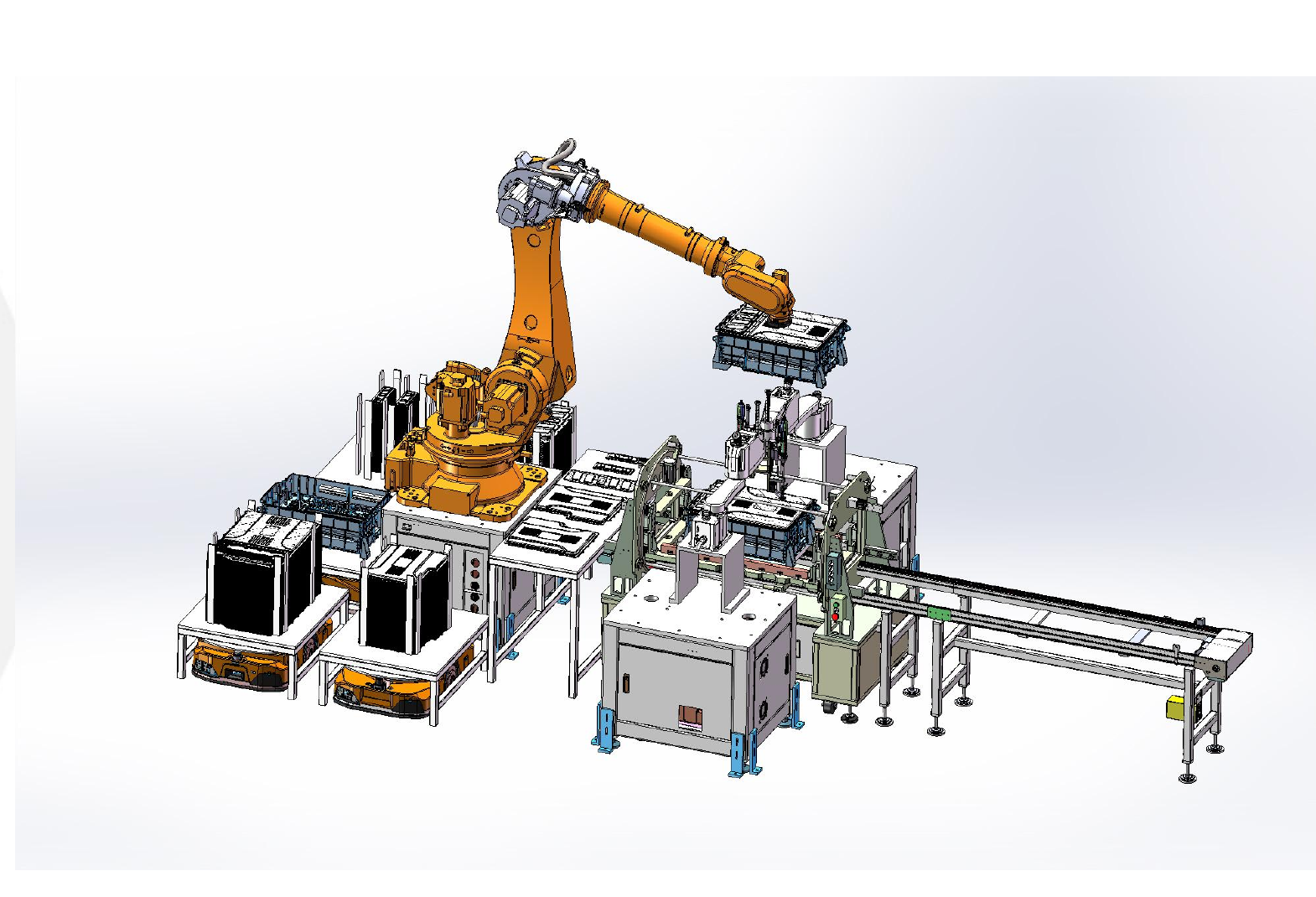
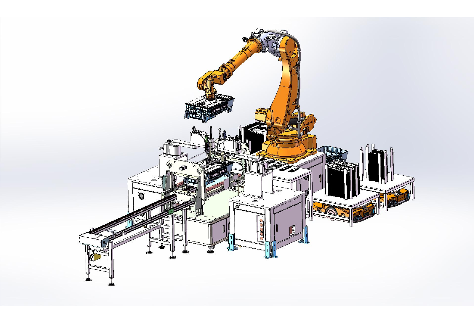
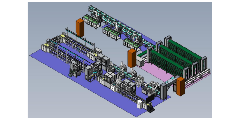
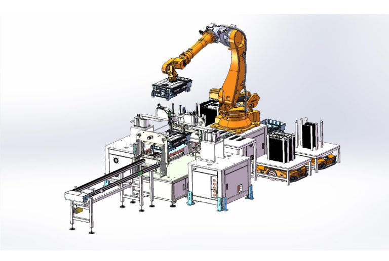
The proposed system places AGV material stations around a guarded robotic cell. A six-axis robot handles the enclosure and component panels, while a dedicated calibration station establishes repeatable pickup and assembly positions. The enclosure is clamped at a rotary fixture so different fastening surfaces can be presented to two four-axis screwdriving robots.
After the screwdriving sequence is completed, the enclosure is transferred out of the cell through the speed-chain conveyor. PLC, touchscreen, and industrial-computer control coordinate robot motion, fixture actions, material flow, and the operating sequence.
AGVs deliver the enclosure and component panels to their assigned staging positions. The six-axis robot picks and transfers the materials through the calibration and assembly sequence. The enclosure is secured at the rotary fixture, where four-axis screwdriving robots A and B complete programmed fastening operations. The finished enclosure then exits through the speed-chain conveyor.
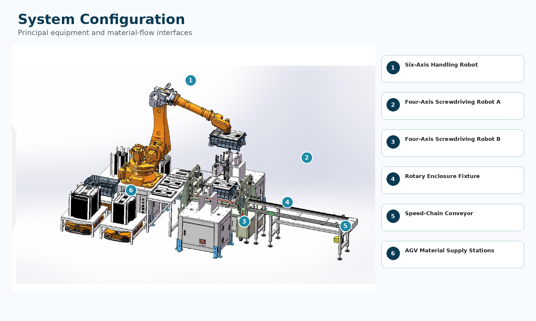
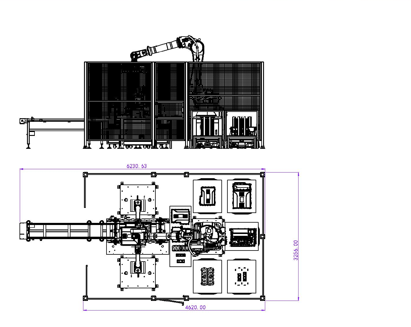
The cell integrates five AGV supply points, one six-axis handling robot, two four-axis screwdriving robots, a component calibration station, a rotary enclosure fixture, and a speed-chain output conveyor
The following equipment functions are derived from the supplied process and structure diagrams.
| No. | Equipment Solution | Role in the System |
| 1 | AGV-Fed Material Supply | Delivers enclosures, bottom covers, top covers, upper sealing plates, and side sealing plates to their designated loading stations. |
| 2 | Six-Axis Handling Robot | Picks the enclosure and assembly components from the AGV stations and transfers them to the positioning and assembly stations. |
| 3 | Enclosure Gripper | Allows the six-axis robot to securely pick, transfer, and position the enclosure during the automated assembly process. |
| 4 | Component Positioning and Calibration Station | Aligns the bottom cover, top cover, upper sealing plate, and side sealing plates before they are assembled onto the enclosure. |
| 5 | Enclosure Fixing and Rotary Station | Clamps and rotates the enclosure so that different fastening positions can be accessed during screwdriving. |
| 6 | Four-Axis Screwdriving Robot A | Performs automated screw fastening at assigned positions on the enclosure assembly. |
| 7 | Four-Axis Screwdriving Robot B | Works with Robot A to complete screw fastening on multiple sides while supporting the required production cycle. |
| 8 | Double-Speed Chain Conveyor | Transfers completed or partially assembled enclosures between the fastening station and downstream production processes. |
| 9 | Safety Enclosure and Maintenance Doors | Separates the robotic operating area from personnel while providing controlled access for inspection and maintenance. |
| 10 | PLC, Touchscreen and Industrial PC | Coordinates AGV material supply, robotic handling, screwdriving, positioning, conveyor operation, and system monitoring. |
The following parameters are taken from the supplied proposal. The main equipment dimensions and the referenced footprint are presented separately because the source document provides both section dimensions and a layout drawing.
| Specification | Value | Notes |
| Front Section Dimensions | 2500 × 1300 × 1850 mm | Reference dimensions for the main body, L × W × H. |
| Rear Section Dimensions | 2500 × 1600 × 1850 mm | Reference dimensions for the main body, L × W × H. |
| Compressed Air Supply | 0.5–0.6 MPa | Required operating air pressure. |
| Power Supply | AC 220V | Required operating power supply. |
| Designed Production Capacity | 600–800 pcs/h | Reference throughput specified for the system. |
| Control System | PLC + Touchscreen + Industrial PC | Used for equipment control, operation, and system monitoring. |
| Required Operators | 1 | One operator is specified for routine system operation. |
Planning an Automated Screwdriving or Assembly Cell?
Contact Robotlyne to evaluate your product structure, material flow, cycle time, equipment scope, and ROI.
Got questions? Ideas? Fill out the form below & our specialist will contact you.
Got questions? Ideas? Fill out the form below & our specialist will contact you.