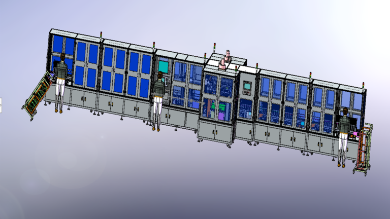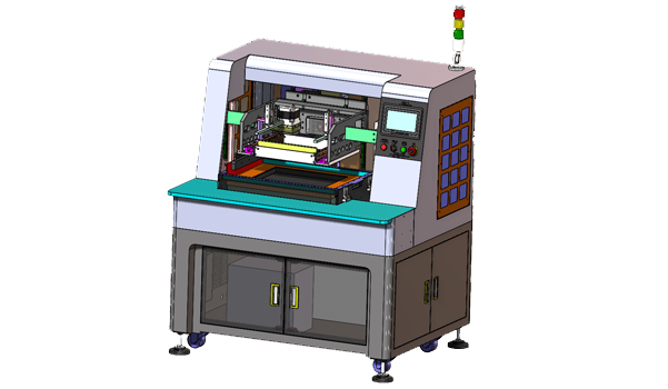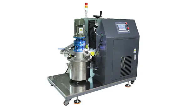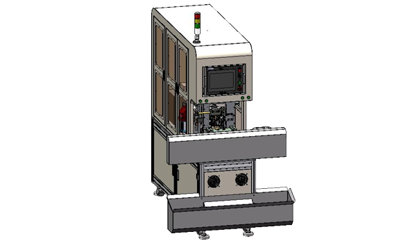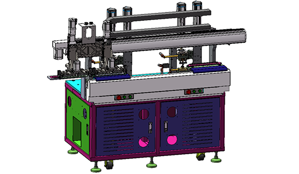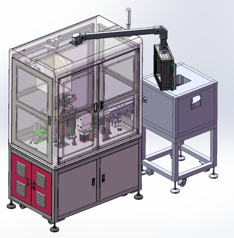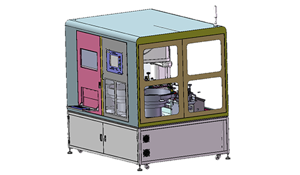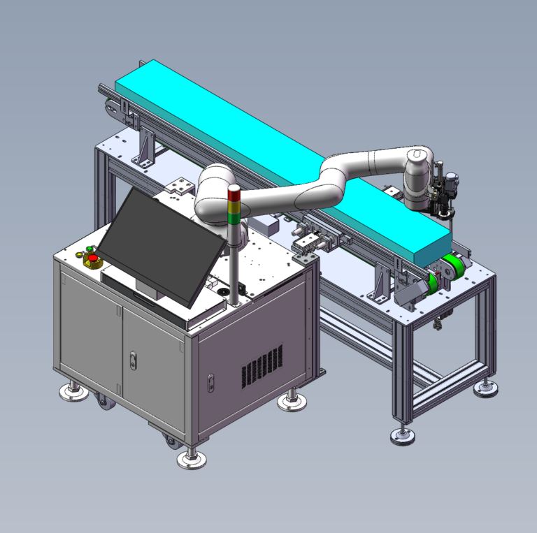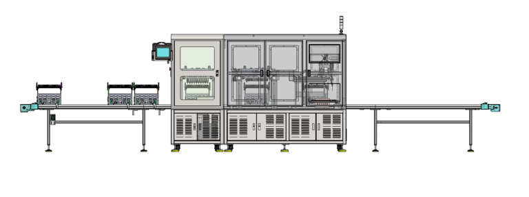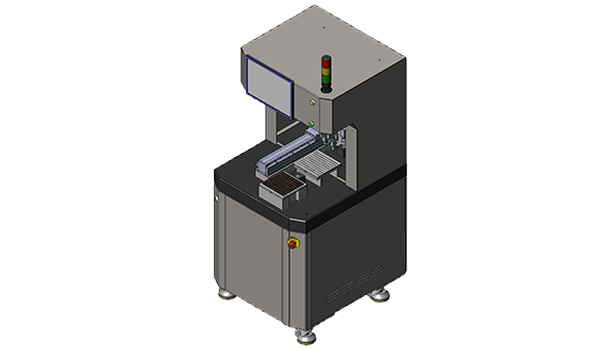
In Home Appliances component manufacturing, Semi-Automatic Assembly Equipment often sits between fully manual assembly and a fully automated production line: the operator handles loading, fixture handling, and process handoffs, while the machine takes over operations that demand higher accuracy and repeatability. In this Semi-Automatic Inductor Copper-Clip Assembly Cell project, Robotlyne needed to place pre-dispensed Copper Clips precisely onto Inductors with a target assembly accuracy of ±0.03 mm, while also preventing outward splay or warpage of the Copper Piece after assembly. The final machine architecture combines CCD Vision, Linear-Motor Motion, a Marble Platform, Fixture-Based Loading, and PLC Control. High-precision placement is assigned to the machine, while Inductor Loading, Copper-Clip Fixture Loading, Curing, and secondary tray changeover remain operator tasks.
Robotlyne’s Electronics Assembly Automation includes Fully Automated, Semi-Automated, and Standalone Equipment for Consumer Electronics and Home Appliances. For products with small part sizes and tight placement requirements, while loading and curing are still well suited to operator involvement, a Semi-Automated Workstation can concentrate automation on the operations that most depend on repeatable accuracy.
±0.03 mm Is Not the Accuracy of a Single Linear Motor
Looking only at the mechanical configuration, it would be easy to treat the assembly requirement as a simple question of whether one motion axis can position to ±0.03 mm.
Robotlyne actually had to manage a complete precision stack.
The planned values include:
Precision Item | Planning Value |
XY Manipulator Positioning | ±0.005 mm |
Rotary Positioning | ±0.01 mm |
Vision Positioning | ±0.005 mm |
Equipment Installation Accuracy | ±0.005 mm |
Environmental Influence | ±0.002 mm |
Theoretical Dual-Vision Accuracy | ±0.032 mm |
The target Placement Accuracy is ±0.03 mm.
Machine accuracy therefore does not come from installing one high-precision Linear Motor. Robotlyne combines CCD Vision, Linear-Motor Motion, a Marble Reference Platform, and PLC + Vision Coordinated Control within the same mechanical architecture.
The Marble Platform provides a stable mechanical reference for both motion and vision.
The Linear Motor controls XY movement.
The Rotary Axis manages assembly orientation.
CCD Vision determines the actual positions of the Inductor and Copper Clip inside their fixtures.
All of these elements converge on one action:
placing the Copper Clip in the correct position on the Inductor.
Any shift in one reference can appear as Placement Error at the final assembly point.
The precision design of this Semi-Automatic Assembly Equipment is therefore built around bringing Mechanical Reference, Motion Control, and Vision Reference into alignment at the placement position.
The Black Inductor Makes Vision Part of the Assembly Mechanism
This project also has a very specific recognition challenge: the Black Inductor.
Robotlyne treated CCD recognition of the black Inductor as a key assembly-stability factor because Copper-Clip Placement depends on both Inductor Recognition and Copper-Clip Recognition.
The machine therefore needs more than knowledge of where the Placement Head is.
It also needs to know:
where the Inductor actually sits in the Fixture
and:
where the Copper Clip to be picked actually sits.
The motion system can then convert those two sets of vision coordinates into an assembly movement.
The sequence can be simplified as:
Recognize Inductor
+
Recognize Copper Clip
↓
Calculate Relative Placement Position
↓
Pick Copper Clip
↓
Place onto Inductor
At a target accuracy of ±0.03 mm, CCD Vision is no longer an optional inspection feature located beside the machine.
It participates directly in Placement.
Vision-coordinate error enters the final assembly result together with Motion Positioning, Rotation, and Mechanical Reference.
Robotlyne therefore uses Dual Visual Recognition instead of relying only on pre-programmed fixture coordinates for Pick-and-Place.
The Fixture provides a repeatable starting position.
Vision then corrects for the actual state of the Inductor and Copper Clip within that position.
The machine executes the placement using the current measured coordinates.
Copper-Clip Tolerance Also Enters the ±0.03 mm Assembly Window
Even when the machine can move the Copper Clip precisely to the target coordinate, the final assembly result still depends on the geometry of the part itself.
The Copper Clip specification includes:
Opening Angle: 90° ±0.3°
The project also considers Inner Opening, Thickness, and Single-Side Angle Tolerance.
The evaluated Inner Opening range is approximately 3.46–3.59 mm.
The finished assembly must also avoid visible outward splay or warpage of the Copper Piece.
The placement result therefore depends on the interaction between two precision systems:
Machine Placement Accuracy
and:
Part Geometry Tolerance
If Copper-Clip Opening, Thickness, or Angle sits toward one end of its tolerance range, the actual mechanical relationship with the Inductor changes as well.
The machine controls where the Copper Clip arrives.
The final assembled condition also depends on whether the Copper Clip geometry creates the intended fit at that position.
Robotlyne therefore included the Copper-Clip tolerance stack in the machine evaluation rather than treating it only as an incoming-quality issue.
At a ±0.03 mm assembly requirement, the Product Drawing and Machine Accuracy have to be considered together.
The Marble Platform, Linear Motor, and CCD make the machine motion repeatable.
The Copper Clip opening geometry determines what that repeatable motion produces mechanically.
A 120-Product Fixture Separates Precision Assembly from the 30-Minute Curing Cycle
Robotlyne did not place the downstream Baking / Curing process inside the same automatic cycle.
The operator first loads the Inductors into the Fixture and then loads the Fixture containing the pre-dispensed Copper Clips.
The machine then performs:
Copper-Clip Pickup
↓
CCD Positioning
↓
One-Side Copper-Clip Assembly
After one side is assembled, the products enter Baking / Curing.
The operator then removes the parts and reloads them into trays before the Copper Clip on the opposite side is assembled. The machine therefore processes one copper-clip side at a time, and a finished two-sided product repeats this sequence.
Each Fixture holds 120 products.
The production plan organizes the Fixture Cycle around:
4 min — fill 120 products
1 min — loading / unloading
5 min — machine assembly cycle before baking
30 min — baking
3 min — cooling
2 min — product removal
From Baking through Product Removal, the cycle is approximately 35 minutes, while the Machine Cycle is about 5 minutes.
The project therefore uses a theoretical circulation requirement of seven Fixtures and adds a 25% reserve, resulting in a plan for 8 Fixtures.
These Fixtures allow the precision assembly machine to continue running instead of waiting for the same batch to complete 30 minutes of Curing.
One Fixture enters Baking.
The next loaded Fixture can enter Machine Placement.
A Fixture that has completed Curing can be unloaded, reorganized, and returned to the downstream flow.
The Semi-Automatic Architecture therefore separates two very different time scales.
The machine handles the short, accuracy-sensitive Copper-Clip Placement step at ±0.03 mm.
Operator handling and Fixture Circulation manage Loading, Curing, Cooling, Removal, and reloading for the second side.
The planned capacity is approximately 1,800–2,000 pcs/hour for one-side Copper-Clip Semi-Finished Products.
After both sides are completed, the corresponding Finished Product output is approximately 900–1,000 pcs/hour.
The value of this Semi-Automatic Assembly Equipment lies in concentrating precision where it matters most. CCD Vision, Linear Motion, and a stable mechanical reference handle the ±0.03 mm placement task, while Fixture Handling and Curing continue on their own production rhythm.
For Home Appliances products such as Inductors, Copper Clips, Terminals, Spring Contacts, or other small components that require high-precision insertion or pressing, and where manual assembly is increasingly affected by Position Accuracy, Part Tolerance, or repeatability, contact Robotlyne to plan the corresponding Semi-Automatic Assembly Equipment around the actual Product Geometry, Tolerance Stack, Vision Requirements, Fixture Capacity, and Curing Process.