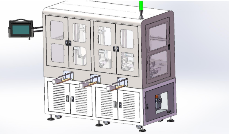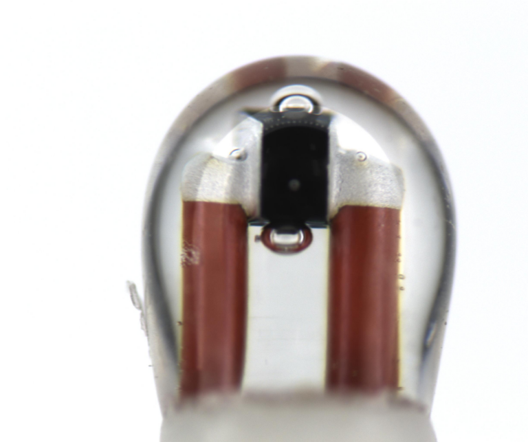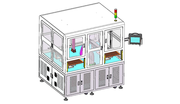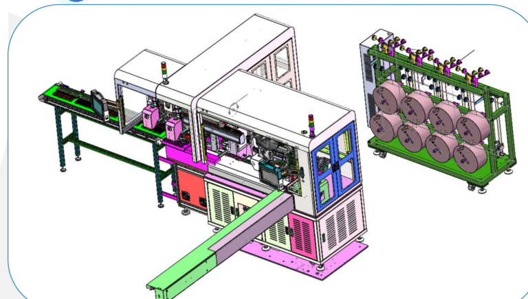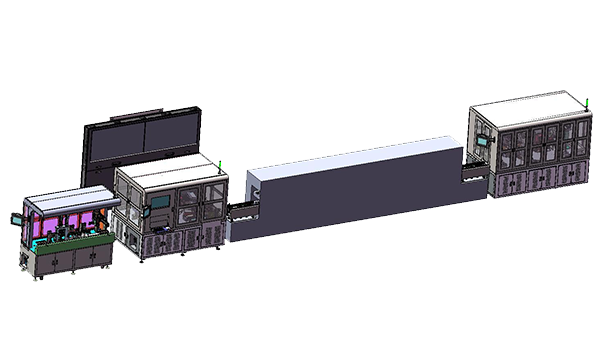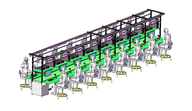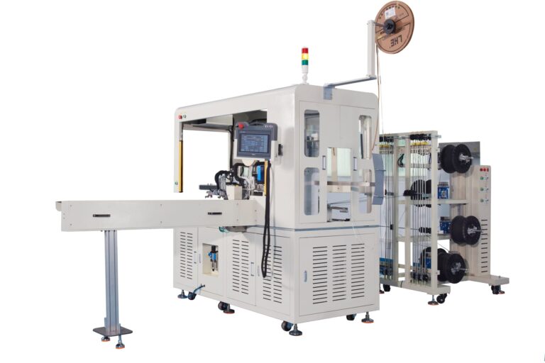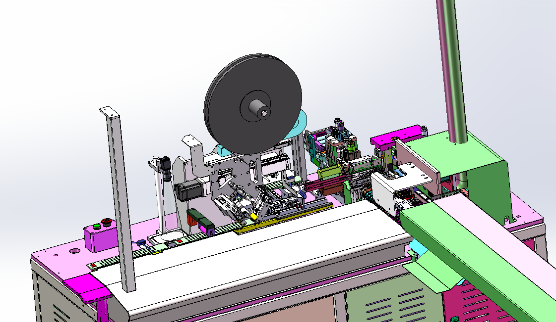
In electronic sensor manufacturing, automated assembly solutions have to preserve the positional relationship between several small components as the product moves from one operation to the next. This Single-End Wire Welding and Assembly Line case connects Wire Cutting and Board Loading, Sleeve Assembly, Single-End Welding, Front/Back CCD Inspection, Tube Pushing, Heat Forming, Bending, Shell Pressing, and final collection in one production route. The line is rated at 600–800 PCS/H with 3 operators.
The product is built from Wire, Sleeve, Welding Components, and downstream forming parts whose relative positions can shift. Stability therefore begins before the welding operation: Wire Straightening, Board Loading, Tape Application, Sleeve Tooling, and component feeding all prepare the geometry that later reaches the Welding Head.
Robotlyne’s Electronics Assembly Automation covers soldering, testing, inspection, encapsulation, and automated or semi-automated workstations for similar multi-process electronics assembly applications.
Once the Wire Is Loaded onto the Board, Every Later Process Inherits That Position
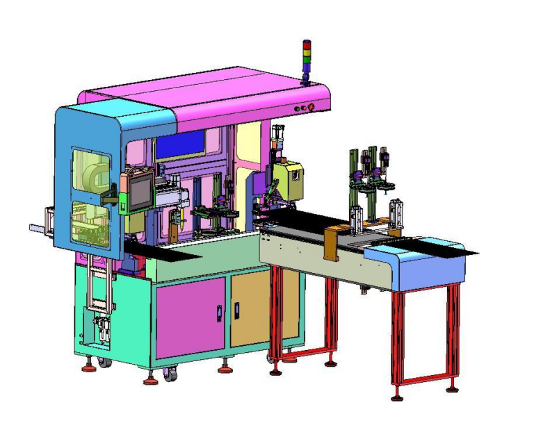
The front end begins with Single-Wire Cutting and Board Loading. The Wire Feeding Rack supplies wire, which is straightened, cut, placed onto a Carrier Board, and fixed with Tape Application. A visual check confirms the wire condition after loading.
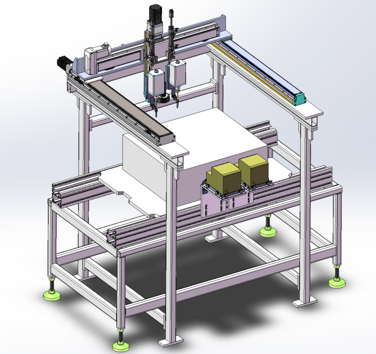
The Carrier Board then becomes the positioning reference for the next operations. Sleeve Feeding and Transfer Tooling place the Sleeve relative to the Wire, and the Sleeve Mold handles 2 Sleeves per Cycle. The Single-End Welding Head introduces another component supplied by a Vibratory Bowl Feeding Group.
Wire Position → Carrier Board Position → Sleeve Position → Welding Component Position → Welded Assembly
Each operation inherits the geometry created upstream. A Wire that shifts on the Board changes the incoming condition for Sleeve Assembly. A Sleeve that moves relative to the Wire changes the geometry presented to the Welding Module. The welding station therefore depends on the stability created by Wire Straightening, Board Transfer, Tape Application, Sleeve Tooling, and component feeding.
Front/Back CCD Inspection Sits Between Welding and Irreversible Forming
After Single-End Welding, the product passes Front-Side and Back-Side CCD Inspection before Tube Pushing, Heat Forming, Bending, and Shell Pressing.
That location creates a practical quality gate. Welding is already complete, but downstream operations have not yet added the tube, thermal forming, bending, or final pressing. A welding defect or missing component can therefore be identified before more processing value is added.
At the line target of 600–800 PCS/H, the Front/Back CCD station operates inside the main production flow. Every welded product passes the two-sided inspection before entering downstream forming, so the vision station is part of the line takt rather than an offline sampling step.
The inspection position also follows the process logic. Welding-related conditions are checked after welding; later forming-related conditions are evaluated after the relevant forming step. The current Front/Back CCD Station therefore closes the welding stage before the product enters deeper mechanical and thermal processing.
600–800 PCS/H Is Tied to a Defined Tooling Family
The line reaches 600–800 PCS/H with 3 operators, but its flexibility is mechanical as well as software-based. When the assembly product changes, all Fixtures need to be replaced and the relevant Components adjusted. Incoming Material Dimensions also need to remain within the corresponding Tolerance Range.
Wire Cutting Length and motion parameters can be adjusted through the machine controls, but a geometry change that affects Fixture interfaces moves changeover into the mechanical domain. The line is therefore designed around a defined family of product structures, with variants supported through fixture replacement and component adjustment.
For stable product families, that approach keeps the production route compact: Wire Cutting, Sleeve Assembly, Welding, CCD Inspection, Tube Pushing, Heat Forming, Bending, and Shell Pressing remain connected without breaking the product into separate machines and manual transfers.
Fixture storage, identification, and setup become part of normal production whenever product variants are changed. The practical operating model is therefore a dedicated multi-process line with controlled changeover, rather than a universal line that runs every sensor geometry without mechanical adjustment.
For electronic sensor automated assembly solutions that combine wire processing, small-component feeding, welding, visual inspection, and downstream forming, Contact Robotlyne to discuss the process sequence, tooling family, inspection positions, and line capacity.