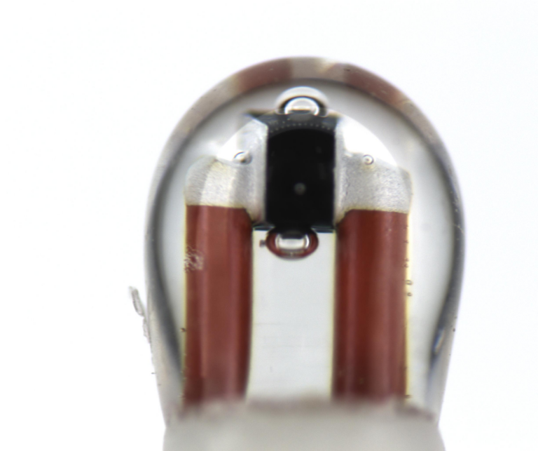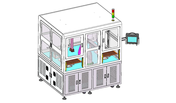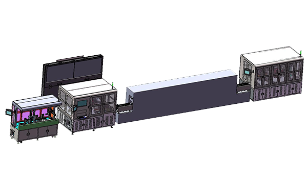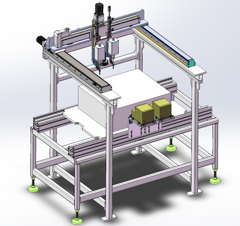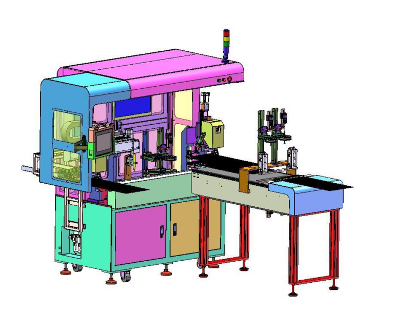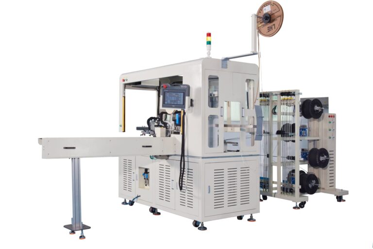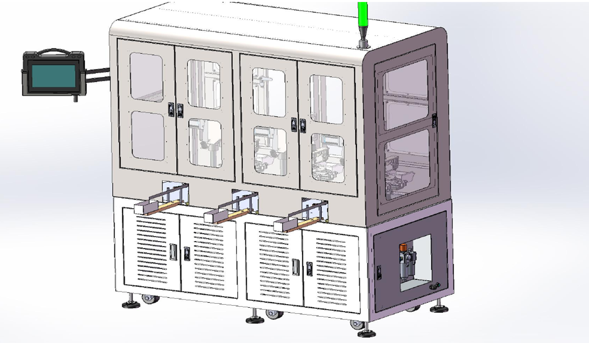
In the sensor industry, Lead Forming equipment often needs to handle components that look similar but differ in lead length, bend position, or final lead geometry. This Taped Varistor Multi-Shape Forming Machine case needed to cover six different forming shapes. Instead of building one dedicated machine for each shape, or forcing every product into a single so-called universal forming mechanism, the project used two machines with three Forming Groups on each machine.
This equipment architecture is useful for analyzing a practical question in multi-variant Lead Forming projects: which mechanisms are worth sharing, and which product differences are large enough to require independent mechanical forming conditions.
Robotlyne’s NTC Sensor Production Automation also includes Feeding, Straightening, Forming, and Lead Cutting modules that can be used to prepare sensor components before welding and assembly.
Six Shapes, but Not Six Machines
The project needed to handle six Forming Shapes. The final architecture was:
2 Machines x 3 Forming Groups per Machine
In other words, each machine keeps three defined forming positions, and the two machines together cover all six shapes.
If the six products were treated as completely separate, the most direct solution would be six dedicated machines. Each machine would have simple Tooling, product paths, and parameters, but Reel Feeding, Cutting, Transfer, PLC, machine frames, and Collection mechanisms would also be duplicated six times.
At the opposite extreme, trying to make one set of Forming Tooling automatically change into six different geometries in the name of flexibility would quickly make the mechanical structure more complicated.
This project takes a middle path.
The way the taped material enters the machine, the separation of components from the paper tape, pickup after cutting, PPU Transfer, and final discharge into the Collection Box can follow the same basic machine logic.
The part that needs to be clearly defined by product Shape is the forming area.
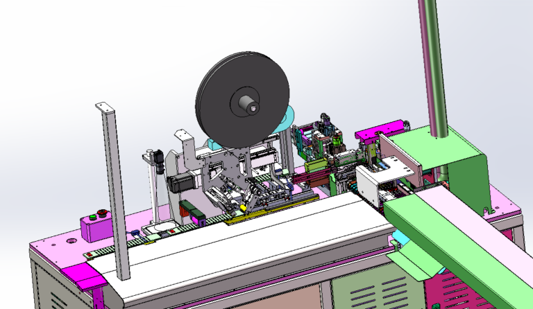
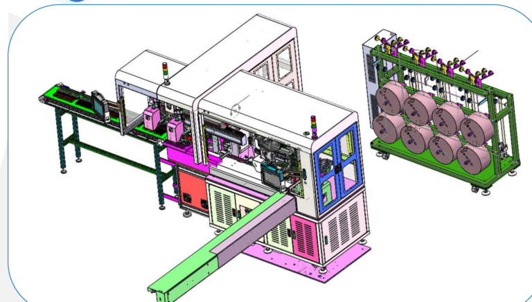
The machine layout uses Forming Group A, B, and C, and the same equipment concept is duplicated across two machines to cover six Forming Shapes. In other words, the shared part is the basic product feeding and transfer architecture, rather than forcing different Lead Geometries to use the same forming die.
This is similar to many sensor component projects. Two models may use the same Reel Format and the same Feeding Mechanism, but if their final Bend Position and lead geometry are different, they are no longer mechanically identical products at the forming stage.
Whether a new Forming Group is needed should therefore be decided by the actual geometry differences, not simply by the number of product models.
How the Lead Shape Is Built Inside a Forming Group
The raw material enters the machine as Reel Tape.
After the operator completes Reel Loading, the Feeding Mechanism automatically advances the taped material into the processing area. The machine first separates the component from the Paper Tape. A transverse transfer mechanism then receives the cut component and clamps it at Forming Position A. A PPU moves the component from Position A to Forming Position B for the next forming stage, and the finished part is then discharged into the Collection Box.
The Lead Geometry is therefore not created by a single bending action.
The case separates Tape Cutting from the downstream Multi-Stage Forming process. The final shape is progressively established at different forming positions.
This creates a continuous relationship between Cutting and Forming.
The Lead Length left after cutting determines how much material is available for the following forming operations. Position A establishes the first stage of the geometry. The PPU transfers the partially formed component to the next position, and Position B completes the remaining shape change.
If Lead Cutting is treated as an isolated preprocessing operation and Forming as a completely separate downstream process, it is easy to miss the fact that both rely on the same product dimensional reference.
The case does not publish Lead Material, Forming Force, or Springback Compensation data, so the required die compensation cannot be calculated from the available information. What the project does confirm is the mechanical concept: the Lead Shape is progressively built through multi-stage Tooling rather than one uncontrolled bend.
The reference capacity is 300-400 pcs/hour with one operator. This figure covers the complete action sequence from reel feeding and cutting to transverse pickup, Position A forming, PPU transfer, Position B forming, and final collection. It is not simply the stroke rate of one Forming Die.
If Position B has not finished processing the previous component, the PPU cannot immediately deliver the next part from Position A. If the cut component has not been removed by the transverse transfer mechanism, the upstream Reel Feeding process cannot continue indefinitely either.
The machine output therefore depends on how these mechanical actions connect with one another, rather than on making a single forming stroke as fast as possible.
A Recipe Can Change Parameters, but It Cannot Change Tooling Geometry
Multi-variant automation projects often involve one easily confused question: which product changes can be handled in software, and which changes require a mechanical change?
If two products use the same basic Forming Tooling and differ only in Cutting Length, motion position, or certain timing parameters, a PLC Recipe may be able to handle part of the changeover.
But the final Lead Form is created through mechanical contact.
Once the product difference involves:
- Lead Spacing
- Bend Position
- Bend Direction
- Final Lead Geometry
software alone cannot turn the existing die into a different geometry.
That is why this case keeps multiple Forming Groups instead of designing a single forming position and claiming that programming alone can cover all six products. The published project scope is limited to the six planned Shapes; it does not present the machine as an infinitely compatible universal former.
For a new sensor Lead Forming project, the product range can first be organized into a Lead Geometry Matrix.
Instead of beginning with the question, “Does the machine need to handle ten models or twenty?”, compare how many genuinely different mechanical shapes exist across those models.
Some products may differ only in length. Others may require only local dimensional adjustments. Still others may belong to the same product family by name while having completely different final Lead Shapes.
The first two groups may be able to share more machine mechanisms. The last group may require a different set of Forming Tooling or even another Forming Group.
Once the products are regrouped by geometry, the required machine count and forming-station count can be planned more rationally than by using SKU quantity alone.
The 2-machine x 3-Forming-Group architecture in this case is a specific result of that tradeoff: six products are not split into six completely independent machines, while each forming condition still keeps a clear mechanical boundary. The project does not publish the actual changeover time between the six Shapes or the Forming Tooling replacement procedure, so the effect of changeover on OEE cannot be calculated from the available information.
The six products ultimately resulted in a 2 Machines x 3 Forming Groups architecture because they were first grouped by Lead Geometry and then evaluated for which mechanical structures could be shared. For a new multi-variant sensor project, this step is usually more useful than deciding the machine quantity first.
When the next step is to turn those product Shape groups into a practical machine architecture, you can contact Robotlyne.