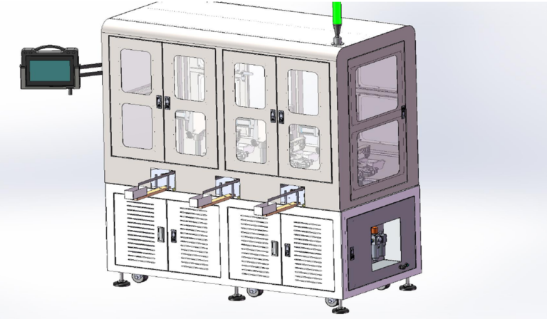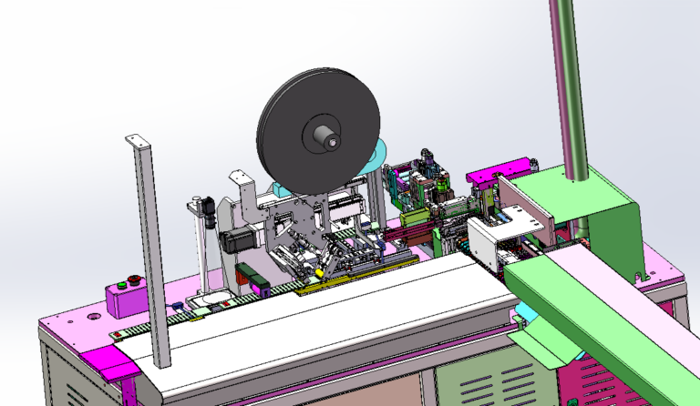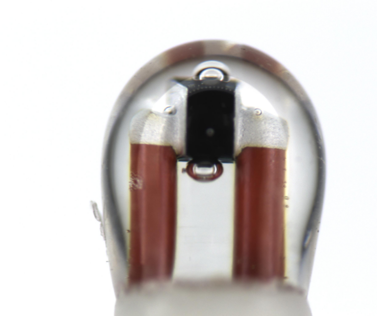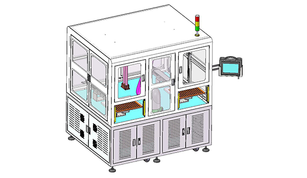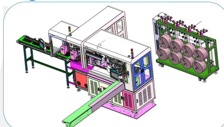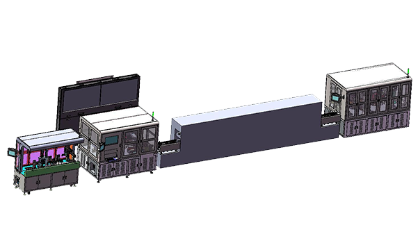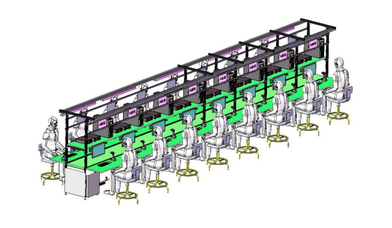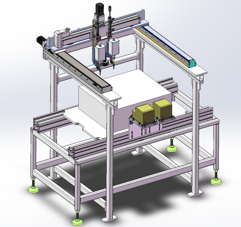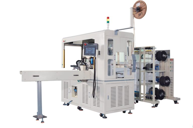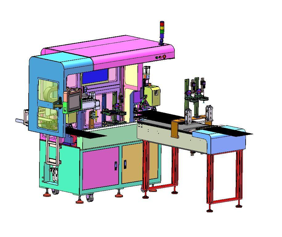
In this finished sensor CCD appearance inspection project, Automated Optical Inspection is positioned after the final heat-press forming process to identify appearance defects that may still remain in the finished product.
The confirmed defect types include:
- cracks in the sensor head;
- missing sensor heads;
- insulation damage on the wire harness;
- wire breakage.
The equipment is designed for a throughput of approximately 1,500–1,800 pcs/hour, with a product wire-length requirement of no more than 200 mm.
But the real challenge in this project is not simply:
finding a CCD camera and taking a picture of the product.
The inspection process needs to include:
Receiving
↓
Wire Arrangement
↓
Light Pressing
↓
Upper / Lower Inspection
↓
Transfer
↓
Front / Back Inspection
↓
NG Marking
↓
Discharge
This means Automated Optical Inspection is not an isolated camera station. It is a complete inspection process that combines product arrangement, material handling, imaging, defect identification, and NG handling.
For similar visual inspection applications, Robotlyne’s Automated Optical Inspection solutions are configured around the product, defect criteria, target cycle time, and production-line constraints rather than around a generic AOI machine.
Why Finished-Product Inspection Cannot Depend Only on Manual Visual Inspection
For finished sensors, many appearance defects are physically small.
Typical examples include:
- Head Cracks;
- Missing Heads;
- Insulation Damage;
- Wire Breakage.
Whether these defects are detected consistently can easily depend on operator condition.
The same product may be judged differently by different operators.
Even the same operator may gradually apply slightly different standards after inspecting large quantities of products continuously.
So the real problem with manual inspection is not:
People cannot see the defect.
It is:
Can the same defect be judged against the same standard consistently across thousands of products?
This is where Automated Optical Inspection provides value.
It converts:
Visual Judgment
that depends on operator experience into:
Repeatable Inspection Criteria
Why the Product Must Be Arranged Before AOI Inspection
The product in this project is not a rigid standalone component.
It includes a wire harness and enters the inspection area as part of a Wire-Board Group.
If the wire harness enters the camera area while it is:
- bent;
- crossed;
- overlapping;
- unstable in position;
then the camera will not see the product in a consistent condition.
This directly affects inspection reliability.
The project therefore includes:
Wire Combing
and:
Light Pressing with a Transparent Plate
before CCD inspection.
In other words, before the system takes an image, it first places the product into a:
Repeatable Presentation
state.
This shows that the first step of Automated Optical Inspection is not:
Take an Image
but:
Present the Product Consistently
Why Product Position Consistency Affects AOI Results
Vision inspection depends on images.
Image quality is influenced not only by the camera and lighting, but also by how the product is positioned.
Suppose the same sensor enters the inspection position three times:
The first time, the wire harness is completely straight.
The second time, part of the harness overlaps.
The third time, the sensor head is slightly rotated.
Even if all camera parameters remain unchanged, the images are already different.
The vision system then needs to compensate for greater:
Position Variation
which increases inspection difficulty.
For products with wire harnesses:
Mechanical Positioning
and:
Vision Inspection
are therefore part of the same system.
If product presentation is unstable, the inspection algorithm must spend more effort compensating for mechanical variation.
Why a Transparent Pressing Plate Is Used
One interesting step in this project is:
lightly pressing the arranged wire harness with a transparent plate.
This action is not intended to process the product.
Its main purpose is to keep the product in a more stable state during visual inspection.
If the wire harness is suspended naturally or bends upward, different products may have different heights.
Height variation can then affect:
- Focus;
- Feature Position;
- Wire Visibility;
- Defect Presentation.
Light pressing reduces this random variation.
At the same time, the transparent structure keeps the inspection path visible to the camera.
So this design is solving a practical problem:
How can the product be stabilized without blocking the areas that the camera needs to inspect?
Why One-Sided Inspection Is Not Enough
The project does not rely on CCD inspection from a single direction.
Instead, it includes:
Upper / Lower Inspection
and:
Front / Back Inspection
This means the product is inspected from multiple directions.
The reason is directly related to the defect types.
For example, a sensor head may appear normal from above while a crack is visible from the side.
Damage to wire insulation may also appear on a:
Camera Blind Side
If only one view is used, the system will naturally contain:
Inspection Blind Spots
So the key question in Automated Optical Inspection is not:
How many cameras are used?
It is:
Do all possible defect locations receive sufficient visual coverage?
Why the Inspection System Should Be Designed from the Defect List
When designing AOI equipment, it is common to begin by discussing:
- Camera Resolution;
- Lens;
- Lighting;
- AI;
But this project highlights a more important starting point:
What Needs to Be Detected
The confirmed defects are:
- Head Cracking;
- Missing Heads;
- Insulation-Layer Damage;
- Wire Breakage.
Only after the defect types are defined can the engineering team determine:
How large is the defect?
Where can it appear?
From which direction must it be viewed?
What contrast is required?
How should the product be presented?
A more appropriate Automated Optical Inspection design sequence is therefore:
Defect Definition
↓
Inspection View
↓
Product Presentation
↓
Optics / Lighting
↓
Detection Logic
rather than selecting a camera first and asking:
What can this camera inspect?
Why More Cameras Do Not Automatically Mean Better AOI
Since multiple inspection directions reduce blind spots, it may seem logical to:
add as many cameras as possible.
But more cameras also mean:
- more image data;
- more trigger signals;
- more lighting combinations;
- more complex calibration;
- more Recipes;
- longer image-processing time;
- greater maintenance complexity.
The real objective of AOI design is therefore not:
Maximum Camera Count
but:
Minimum Views Required for Complete Defect Coverage
The upper/lower and front/back inspection concept in this project is essentially a multi-angle coverage strategy built around the actual defect distribution of the product.
Why 1,500–1,800 PCS/H Is More Than Camera Shooting Speed
The planned machine throughput is approximately:
1,500–1,800 pcs/hour
But a complete Inspection Cycle includes much more than:
Camera Exposure
It also includes:
- upstream product receiving;
- Wire-Board Group advancement;
- wire arrangement;
- transparent-plate pressing;
- upper/lower inspection;
- transfer receiving;
- front/back inspection;
- NG marking;
- product discharge.
So the factor that limits equipment throughput is:
Complete Inspection Cycle
not:
Camera FPS
This is why Automated Optical Inspection Equipment cannot be evaluated only by comparing camera specifications.
The vision system may be very fast, but if the mechanical handling process cannot keep up, total machine throughput will not increase.
Why the Transfer Mechanism Is Part of the AOI System
After upper/lower CCD inspection, the product in this project needs to move through a:
Transfer Receiving Head
into the next Receiving Tray before front/back inspection.
So the product moves between two separate Inspection Zones.
This transfer must achieve two things:
Move the Product
and:
Do Not Destroy the Inspection Position
If the transfer causes:
- sensor-head rotation;
- the wire harness to become tangled again;
- significant position changes;
then the Product Presentation established earlier is lost.
The goal of the Transfer Mechanism is therefore not only:
Transport
It is also:
Maintain Inspection State
Why Wire Length Affects Automated Optical Inspection Equipment Design
The confirmed Wire-Length Requirement in this case is:
≤ 200 mm
At first glance, this parameter may appear unrelated to the vision system.
In practice, it directly affects:
- Wire Arrangement Area;
- Carrier Size;
- Transfer Stroke;
- Camera Field of View;
- Machine Footprint;
- Wire Overlap Probability.
The longer the wire, the greater the positional variation when the product is unconstrained.
For sensor inspection applications with wire harnesses:
Wire Length
is therefore an input condition for AOI mechanical design.
When product specifications change, the engineering team cannot ask only:
Has the sensor-head size changed?
It also needs to confirm:
Are the wire length and wire form still compatible with the current handling and inspection layout?
Why NG Handling Does Not Necessarily Need Fully Automated Sorting
After identifying an NG product, the project uses:
NG Marking
The product then continues to discharge, after which the operator performs:
Manual Take-Away
The system therefore does not add a complex automatic NG robot sorting system simply to achieve a higher degree of automation.
This is a practical engineering trade-off.
If the AOI system can already make a reliable:
OK / NG Decision
then whether NG products must be removed automatically depends on:
- NG Rate;
- Product Value;
- Handling Difficulty;
- Line Takt;
- Labor Requirement;
- Sorting Complexity.
If NG quantity is low, adding a dedicated automatic sorting mechanism may provide limited value.
In that situation:
Automatic Detection + NG Marking + Manual Removal
may be the simpler and more practical solution.
Why Automatic Inspection and Automatic Loading/Unloading Are Different Levels of Automation
The project still retains:
Manual Unloading
But this does not mean the Automated Optical Inspection process is incomplete.
The core inspection functions:
- product receiving;
- product positioning;
- multi-angle visual inspection;
- NG decision;
- NG marking;
are already automated.
The operator only removes the final product.
The appropriate automation level for an AOI project should therefore be determined by the actual bottleneck.
If the main quality risk comes from:
Manual Inspection
then automating the inspection process itself already addresses the core problem.
There is no need to automate every handling step simply to make the equipment appear more automated.
Why Finished-Product AOI Has a Different Objective from In-Process AOI
Automated Optical Inspection can be used at many different points in a production process.
For example:
After Welding
to inspect weld quality.
Or:
After Assembly
to check component presence and position.
This project is different because it is a:
Finished-Product Appearance Inspection
station.
The product has already completed heat-press forming, and the inspection focuses on finished-product conditions such as:
- head integrity;
- appearance cracks;
- wire-harness insulation;
- wire breakage.
It is therefore closer to a:
Final Visual Quality Gate
Its purpose is not to tell an upstream robot:
How far was the assembly position off?
It is to determine:
Does the completed product still meet the required appearance standard?
Different AOI positions may use CCD cameras, but the camera configuration and control logic can be very different depending on the actual inspection objective.
Why the Equipment Size Reflects the Complexity of Inspection Coverage
The confirmed equipment dimensions are approximately:
1,900 × 2,250 × 1,910 mm
For a “vision inspection machine,” this is much more than a simple Camera Box.
The machine needs to accommodate:
- Receiving Module;
- Transfer Head;
- CCD Inspection Modules;
- Marking Module;
- Discharge Module;
- Material Tray;
- Storage Support Frame;
So the floor space of Automated Optical Inspection Equipment is not determined only by the cameras.
Most of the machine footprint comes from:
the complete mechanical process required to present the product correctly to every inspection view.
Why AOI Ultimately Designs a Repeatable Decision Process
Looking only at the equipment, the project could be described simply as:
using CCD cameras to inspect sensor appearance.
But the complete system is actually:
Product Received
↓
Product Arranged
↓
Product Stabilized
↓
Upper / Lower Inspection
↓
Controlled Transfer
↓
Front / Back Inspection
↓
NG Decision
↓
NG Marking
↓
Discharge
True Automated Optical Inspection is not simply replacing the human eye with a machine.
It establishes a quality judgment process based on:
the same product presentation + the same observation conditions + the same defect criteria + the same handling logic
That repeatability is what allows AOI to reduce variation in manual judgment during high-volume production.
Planning an Automated Optical Inspection Project?
Robotlyne can evaluate your product geometry, defect criteria, inspection views, handling method, target cycle time, and production-line interface. Contact Robotlyne to discuss your AOI application.