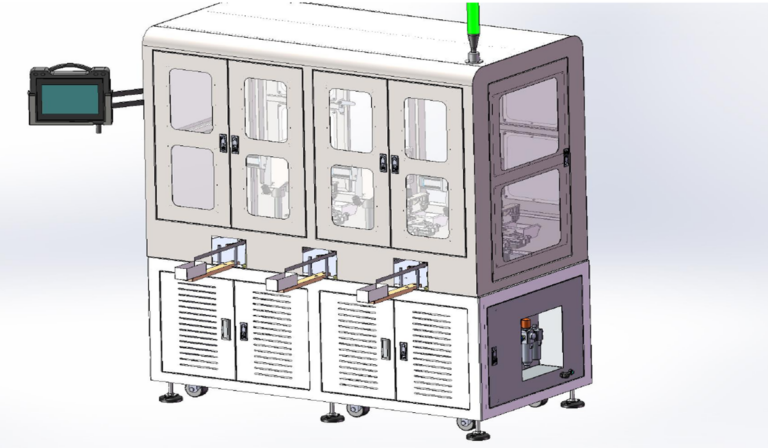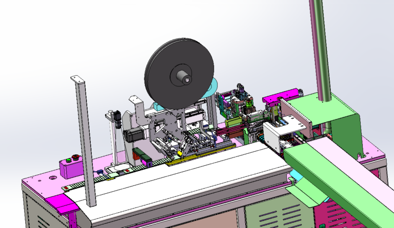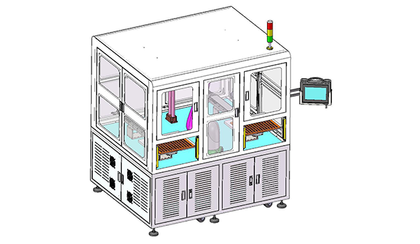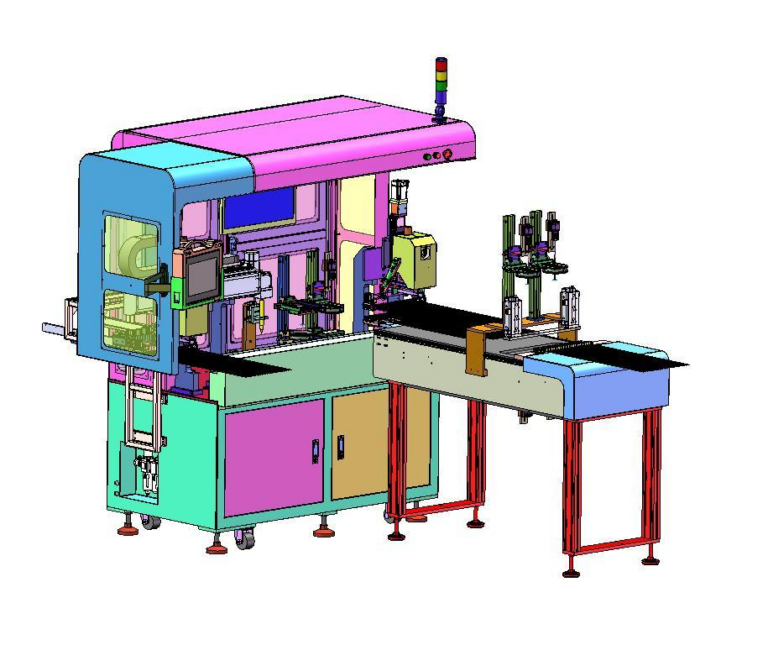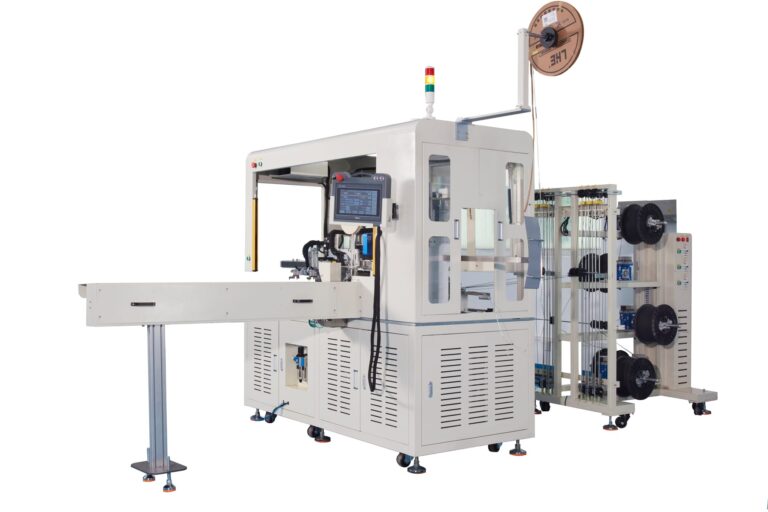
PCB surface dust removal may look like a very simple process in electronics manufacturing, but reliable Automatic Dust Removal Equipment has to control much more than airflow alone.
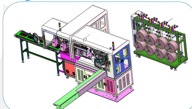
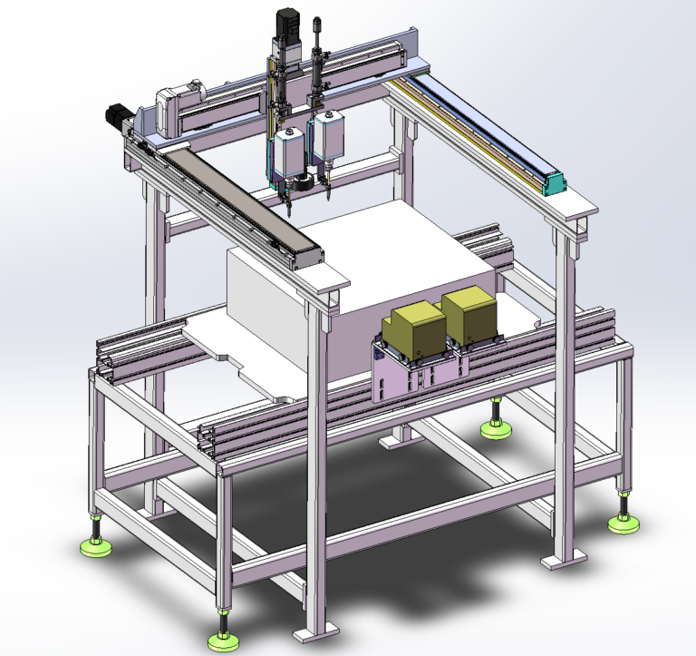
This article draws on a PCB automatic dust removal workbench project, where the key engineering challenge was not simply generating airflow, but creating a controlled and repeatable cleaning process around PCB positioning, particle removal, dust extraction, and production-line integration.
Once it is turned into an automated workstation, however, the challenge is no longer just:
How do we blow dust off the PCB?
The real question is:
How can each PCB enter the cleaning station in a consistent position, be cleaned without damaging the board or electronic components, and have the released particles controlled so they do not settle back onto the PCB or spread into the surrounding production environment?
This is one of the main differences between purpose-built Automatic Dust Removal Equipment and simple manual air blowing.
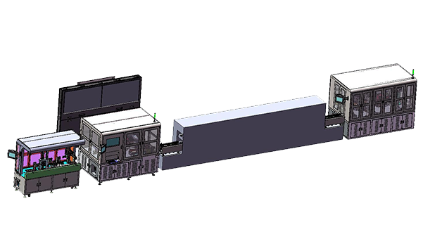
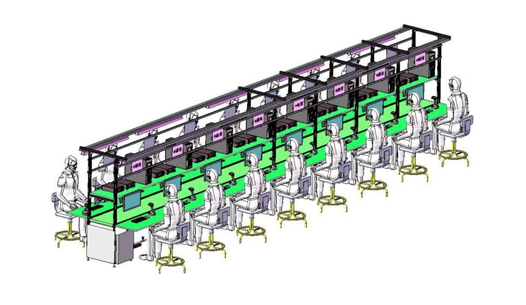
For electronics manufacturers, this type of workstation is usually not an isolated piece of equipment. It is one process node within a broader electronics assembly automation flow. Robotlyne’s electronics assembly automation capabilities cover standalone machines, semi-automated workstations, and fully automated production systems, so a PCB dust removal workbench can also be integrated in different ways depending on production takt and upstream/downstream interfaces.
Why PCB Dust Removal Is More Than Just Blowing Air
The most direct way to clean a PCB is usually to use airflow to remove dust and particles from the board surface.
But this creates a practical problem:
Dust Removed from the PCB does not mean Dust Removed from the Process.
Once dust leaves the PCB surface, if it is not controlled, it may:
- spread inside the workstation;
- settle onto another PCB;
- reattach to a surface that has just been cleaned;
- enter nearby equipment;
- increase particle contamination around the work area.
For Automatic Dust Removal Equipment, the cleaning process therefore needs to consider two actions:
Dust Separation
and:
Dust Collection
The first action removes particles from the PCB surface. The second removes those particles from the work area.
If the system only blows dust away without collecting it effectively, the machine may simply move contamination from one location to another.
Why PCB Positioning Directly Affects Cleaning Performance
One important difference between automated cleaning and manual cleaning is that the machine must repeat the same action on every PCB.
That means each PCB should enter the cleaning zone in a consistent position.
The design needs to consider:
- PCB outline dimensions;
- whether a carrier or fixture is used;
- board orientation;
- cleaning area;
- component height;
- whether certain areas should not be exposed to strong direct airflow.
If PCB position changes significantly from cycle to cycle, a fixed nozzle or cleaning mechanism may cause:
Over-cleaning in some areas
while other areas receive:
Insufficient cleaning coverage.
So the workstation cannot be designed around the cleaning mechanism alone.
It must also include:
Product Positioning
because stable product position is what makes the cleaning action repeatable.
Why Stronger Airflow Is Not Always Better
A common reaction to incomplete dust removal is:
If the dust is not coming off, increase the air pressure.
But a PCB is not an ordinary metal plate.
It may already contain:
- Connectors;
- Sensors;
- Small Components;
- Leads;
- Flexible Elements;
- Labels or other attached items.
Excessive airflow may provide little additional cleaning benefit while increasing:
- force on small components;
- movement of loosely positioned material;
- high-speed particle rebound;
- secondary dust dispersion.
The parameters that actually need to be controlled are:
Airflow + Distance + Angle + Exposure Time
rather than simply maximizing air pressure.
For automated equipment, the more important objective is to establish a:
Repeatable Cleaning Window
so that every PCB experiences similar cleaning conditions.
Why Nozzle Position Must Be Designed Around the PCB Structure
PCB surfaces are not all the same.
Some areas are relatively flat.
Some contain taller components.
Some have narrow gaps between components.
This means blowing from only one fixed direction may not clean every area effectively.
Nozzle design needs to consider:
- airflow direction;
- distance between nozzle and PCB;
- component height;
- areas where dust tends to accumulate;
- whether any surfaces are shielded by components.
The real design goal is not:
Maximum Air Coverage
but:
Effective Dust Removal from the Critical Surface Areas
If the workstation must handle multiple PCB models, product variation may further affect nozzle layout and fixture design.
Why Released Dust Must Be Controlled Immediately
Once dust leaves the PCB surface, it becomes airborne.
If the workstation does not create a controlled airflow pattern, released particles may circulate inside the cleaning area.
This can create a cycle of:
Blow -> Suspend -> Resettle
In other words: the particles are blown off, remain suspended, and then settle again.
For this reason, air blowing and dust extraction should not be treated as two completely separate functions.
A better approach is to coordinate:
Blowing Direction
with:
Extraction Direction
After the cleaning mechanism releases particles from the PCB surface, the extraction airflow should carry them away from the product area as quickly as possible.
This is what helps reduce secondary contamination.
Why the Cleaning Area Needs to Be Controlled
If dust removal takes place in a completely open environment, particle movement becomes much harder to control.
From an equipment-design perspective, a more controlled cleaning zone helps limit:
- Dust Dispersion;
- Airflow Leakage;
- Secondary Contamination.
It also makes it easier to concentrate extraction around the effective cleaning area.
However, enclosure design cannot consider dust control alone.
It also needs to account for:
- loading and unloading convenience;
- operator visibility;
- equipment maintenance;
- product changeover;
- removal of accumulated dust.
So the goal of a workbench enclosure is not simply:
Seal Everything
It is:
Control the Cleaning Environment while Keeping the Station Accessible
Why the Workbench Itself Must Be Easy to Clean
A dust removal machine will also accumulate dust over time.
Common accumulation points include:
- conveying surfaces;
- positioning fixtures;
- the inside of protective covers;
- areas near extraction inlets;
- filtering and collection areas.
If the machine itself is difficult to clean, it may eventually become a new source of contamination.
Maintainability therefore needs to be considered from the beginning.
The design should make it convenient to:
- open the cleaning area;
- replace or clean filter components;
- clean the dust collection area;
- wipe positioning mechanisms;
- inspect nozzles and air lines.
Stable operation does not mean only that the workstation performs well immediately after commissioning.
It means:
After extended production, the machine can still be returned to normal cleaning performance without excessive maintenance effort.
Why Changeover Capability Depends on How Different the Products Are
If the workstation handles only one fixed PCB model, the entire design can be optimized around that product.
If multiple PCB sizes are used, the workstation also needs to consider:
- Width;
- Length;
- Component Height;
- Cleaning Area;
- Fixture Type.
When product differences are small, adjustable positioning mechanisms may be sufficient.
When the differences are larger, separate fixtures may be more appropriate.
Multi-product compatibility therefore does not mean:
One universal workstation that never needs adjustment.
A more practical approach is:
Standard Machine Platform + Product-Specific Positioning
This keeps the main equipment architecture consistent without sacrificing positioning and cleaning stability in the pursuit of complete universality.
Why a PCB Dust Removal Station Must Consider Upstream and Downstream Takt
If the workstation is used as standalone equipment, an operator can load a PCB manually, run the cleaning cycle, and remove it afterward.
In that case, machine cycle time is relatively independent.
Once the dust removal workbench is integrated into an automated production line, the situation changes.
The relationship becomes:
Upstream Output
then:
PCB Dust Removal
then:
Downstream Process
If the dust removal station is slower than the surrounding processes, it becomes a:
Bottleneck
So an automatic dust removal system cannot be evaluated only by asking:
Can it clean one PCB effectively?
It also needs to answer:
How many PCBs can it process consistently per hour while maintaining the same cleaning performance?
That is one of the key differences between standalone cleaning equipment and production automation equipment.
Why 'Cleaning Complete' Needs a Defined Process Logic
With manual cleaning, an operator can look at the board and decide:
It looks clean enough.
Automated equipment needs a more explicit cycle logic.
At minimum, the system needs to confirm:
- whether the PCB is in position;
- whether the cleaning action has been executed;
- whether the air supply or cleaning mechanism is operating normally;
- whether the dust extraction system is operating normally;
- whether the PCB is allowed to leave the station.
If these conditions are not confirmed, the machine may continue automatically even when:
Product Moves Forward Without a Valid Cleaning Cycle
A reliable automated workstation therefore needs more than actuators.
It also needs:
Process Confirmation
Why Fault-Recovery Logic Is Part of the Workbench Design
In real production, the workstation may encounter:
- a PCB that is not positioned correctly;
- an air-supply fault;
- an extraction-system fault;
- a jammed product;
- an open guard;
- a downstream station that cannot accept the product temporarily.
If every abnormal condition requires an engineer to enter the PLC or restart the entire machine, availability will suffer.
The workstation therefore needs a recovery sequence such as:
Alarm -> Diagnosis -> Reset -> Resume
Operators should be able to understand:
- what fault occurred;
- where the current PCB is located;
- whether the current cleaning cycle has been completed;
- which step the workstation should resume from after reset.
The higher the level of automation, the more important fault-recovery design becomes.
Why Automatic Dust Removal Equipment Is More Than a Cleaning Machine
From the equipment name alone, it is easy to think of the system as:
An automatic workbench that blows dust off PCBs.
But a stable production machine actually needs to connect:
Product Positioning
then:
Dust Separation
then:
Dust Extraction
then:
Cycle Control
then:
Product Transfer
If the workstation will later be integrated into an automated production line, it also needs to consider:
Upstream / Downstream Interface
So the real design object is not:
A Dust Blower
but:
A Controlled PCB Cleaning Process
That is the real value of an automatic dust removal workbench compared with simple manual air blowing.
Planning a PCB Cleaning or Electronics Automation Project?
Robotlyne can evaluate your PCB handling, cleaning process, workstation layout, cycle-time requirements, and production-line integration needs. Explore Robotlyne’s electronics assembly automation solutions to discuss your application.