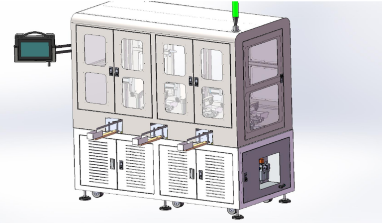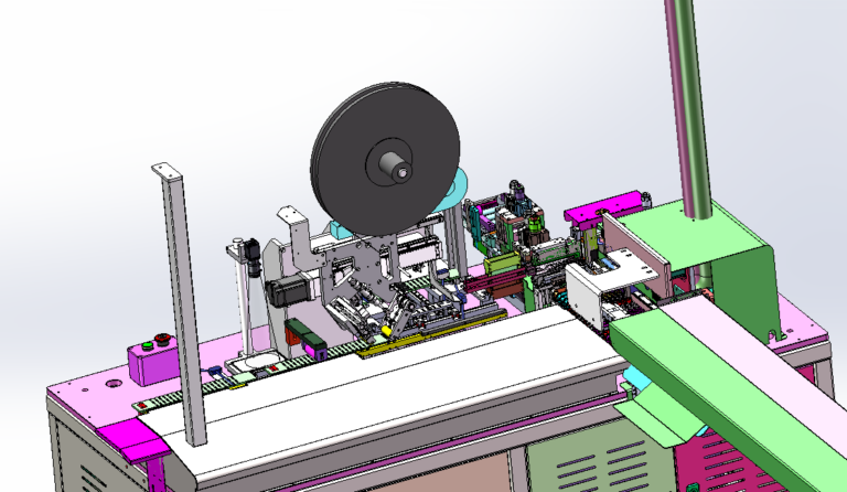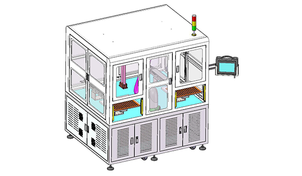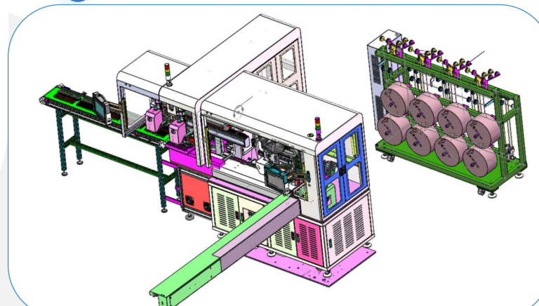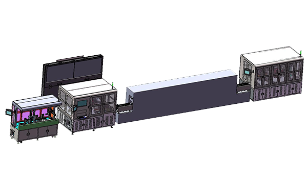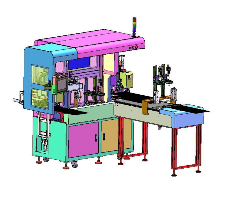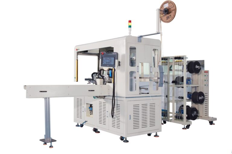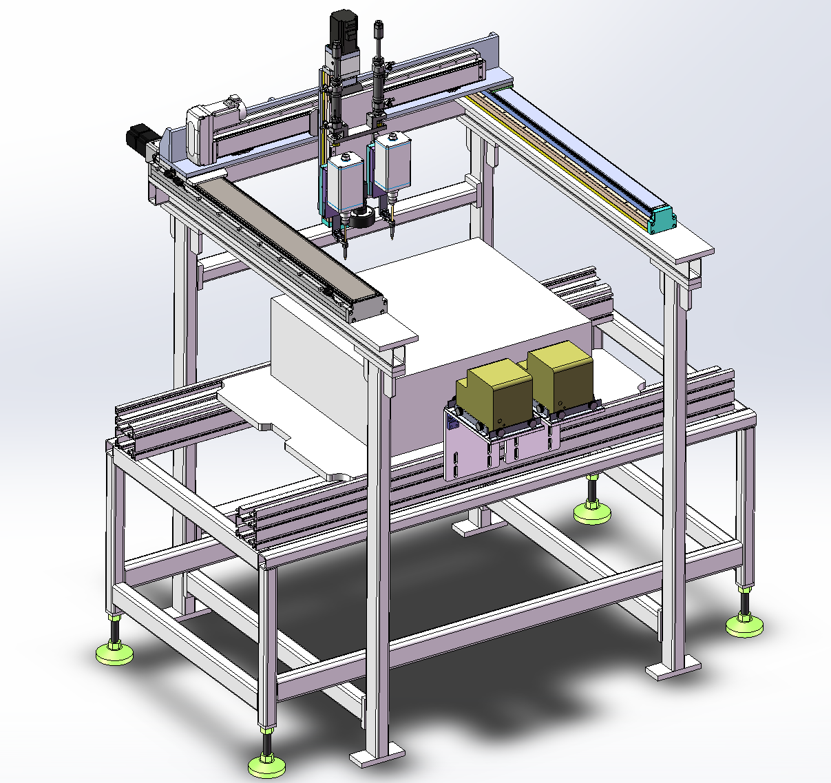
In this inline dual-head Screw Fastening project, the machine needed to integrate directly into a tray-conveyor production line while supporting different screw sizes, including M4, M5, and M6.
The complete equipment flow includes:
Tray Conveying
↓
CCD Position Recognition
↓
X / Y / Z Positioning
↓
Dual-Head Screw Fastening
↓
Product Discharge
Depending on the workstation requirements, the screw feeding system can be configured with 1, 2, 3, 4, or 6 Screw Feeders. The planned output is approximately 600–900 PCS UPH, but actual board-level UPH decreases as the number of feeders increases.
So the real question behind this project is not:
“Do two fastening heads automatically make the machine twice as fast as one?”
It is:
How can dual-head fastening, CCD positioning, tray conveying, and different screw-feeder configurations work together while keeping equipment size and total cycle time within a practical range?
For similar applications, Robotlyne’s Automated Screwdriving & Fastening solutions are configured around the product, screw specifications, fastening positions, feeding method, and required production takt rather than around a standalone electric screwdriver.
Why This Machine Uses Dual-Head Fastening Instead of a Single Screwdriver
If a product has only one screw, a single fastening head is usually sufficient.
But once a product includes multiple Screw Fastening Positions, every screw requires the system to repeat:
Move
↓
Position
↓
Receive Screw
↓
Fasten
↓
Move to Next Position
If one head performs every fastening task, total cycle time increases as the number of screws increases.
This project therefore uses:
Dual-Head Screw Fastening
The basic idea is to parallelize part of the fastening workload.
But the value of a dual-head design is not simply:
2 Heads = 2× Speed
Both heads are still affected by:
- screw-hole distribution;
- X/Y/Z travel time;
- Screw Feeder supply;
- CCD positioning;
- mechanical clearance between heads.
The real optimization problem is:
how the fastening workload is divided between the two heads.
If Head A performs most of the screws while Head B handles only a small number, the dual-head structure is not being used efficiently.
The benefit therefore depends on:
Fastening Task Balance
not just the number of fastening heads.
Why Screw Fastening Cycle Time Cannot Be Estimated from Screwdriver RPM Alone
The planned capacity of the machine is:
600–900 PCS UPH
which corresponds to a total product cycle of roughly:
4–6 seconds per piece
But the actual machine cycle includes much more than screw rotation.
It also includes:
- tray entry;
- tray positioning;
- CCD recognition;
- X/Y/Z movement;
- Screw Feeding;
- fastening;
- dual-head switching or synchronized motion;
- product release;
- tray exit.
So using only:
Screwdriver RPM
to estimate UPH can significantly overstate actual machine capacity.
For automated Screw Fastening, the correct calculation needs to cover the full sequence:
Product In → Position → Vision → Feed → Fasten → Product Out
In other words:
Fast Screwdriver ≠ Fast Screw Fastening Machine
Why the Project Uses CCD Position Recognition
The product enters the machine through Tray Conveying.
In theory, if every tray and every product were positioned exactly the same way, the machine could fasten using fixed coordinates.
In real production, however, there may be:
- Tray Position Variation;
- Product Position Variation;
- Fixture Tolerance;
- Assembly Tolerance.
If the fastening heads move only to nominal coordinates, these variations are transferred directly into the Screw Fastening Process.
Possible results include:
- the bit missing the screw hole;
- angled screw insertion;
- failure to engage the thread correctly;
- bit slippage;
- damage to the screw head or product.
This project therefore adds:
CCD Position Recognition
before fastening.
The control logic changes from:
Move to Nominal Coordinate
to:
CCD Detects Actual Position
↓
Coordinate Correction
↓
Screw Fastening
The CCD is not added simply to make the machine more visually sophisticated.
It solves a practical problem:
How can the fastening head still find the correct screw position when small product-position variations exist in continuous tray production?
Why Tray Positioning and CCD Cannot Replace Each Other
Once CCD is available, it may seem reasonable to think:
Mechanical positioning can be made less precise.
That is not the case.
If the tray position varies too much every time it enters the machine, the CCD system needs a larger search range and greater compensation.
Vision is better suited to correcting:
Small Position Variation
rather than replacing the mechanical positioning system entirely.
A more stable relationship is:
Mechanical Positioning
first controls the product within a repeatable range,
then:
CCD Correction
compensates for the remaining variation.
In other words:
Coarse Mechanical Positioning + Fine Vision Correction
If the mechanical foundation is unstable, the vision system has to compensate for excessive random variation, which can reduce both cycle speed and system stability.
Why M4, M5, and M6 Make the Feeding System More Complex Than the Fastening Heads
This project needs to support:
M4
M5
and:
M6
Different stations may use different screw combinations, including:
- M4 + M5;
- M4 + M6;
- M5 + M6.
This means one universal Screw Feeder cannot necessarily supply every fastening head.
Different screw sizes usually require separate:
Feeding Paths
and:
Presentation Positions
As the number of screw types increases, the surrounding feeding system becomes larger and more complex.
That is why the real machine architecture is not simply:
Dual-Head Screwdriver
but:
Dual-Head Fastening Platform + Configurable Screw Feeding System
Why Feeder Quantity Directly Changes Machine Size
The case provides reference dimensions for different Feeder Configurations.
1–2 Feeders
Approximately:
1,050 × 1,140 × 1,752 mm
3 Feeders
Approximately:
1,300 × 1,140 × 1,752 mm
4 Feeders
Approximately:
1,450 × 1,140 × 1,752 mm
6 Feeders
Approximately:
1,900 × 1,140 × 1,752 mm
As the number of Feeders increases, machine length grows from about:
1,050 mm
to:
1,900 mm
which is close to double.
The reason is straightforward.
Every additional feeding combination requires more space for:
- Feeders;
- Screw Tracks;
- Pickup Positions;
- Maintenance Access;
- Pneumatic / Electrical Connections.
So when planning a Screw Fastening Station, it is not enough to ask:
How large is the product?
You also need to ask:
How many screw types are required, and how many feeding modules does each screw type need?
In some projects, the real factor that determines Machine Footprint is not the product.
It is the:
Feeder Configuration
Why More Feeders Can Reduce UPH
The case specifically states that:
Board-Level UPH decreases as feeder quantity increases.
This is worth paying attention to.
At first glance, adding more Feeders may seem like it should make the machine faster because:
more screws are available at the same time.
In practice, more Feeders often mean:
- more screw types on the product;
- more fastening positions;
- more screw pickup actions;
- longer X/Y/Z travel paths;
- more complex workload distribution between the two heads.
So:
More Feeders
often means:
More Fastening Work
and therefore a longer total cycle.
This means:
600–900 PCS UPH
should not be treated as one fixed value for every configuration.
Actual capacity needs to be calculated from:
Screw Quantity + Screw Type + Fastening Positions + Feeder Count + Motion Path
Why 900 UPH Should Not Be Used as a Universal Capacity Claim
The case gives a planned range of:
600–900 PCS UPH
and also states that the final value depends on the actual application and Feeder quantity.
A configuration with:
1 Feeder
and only a few fastening positions may operate closer to the higher end of the range.
A:
6-Feeder Configuration
with more Screw Fastening Positions may operate at a lower actual UPH.
For this type of custom automation equipment, a more accurate specification is therefore:
Capacity Range
rather than:
Guaranteed Fixed UPH for Every Product
The final value should only be confirmed after defining:
- Product;
- Screw Map;
- Screw Quantity;
- Feeding Method;
Why Different Stations Can Share the Same Dual-Head Core
The case includes workstations with:
1, 2, 3, 4, and 6 Feeder Groups
while the core fastening architecture remains:
Dual-Head Fastening + CCD + X/Y/Z Motion
This reflects a practical modular design strategy.
Instead of designing a completely different machine for every product, the project keeps a relatively stable:
Fastening Core
and changes the:
Feeder Module
according to the workstation requirements.
The architecture can be understood as:
Standard Core + Configurable Peripherals
The core platform handles:
- Motion;
- Vision;
- Fastening;
- PLC Control.
The surrounding modules are configured with different Screw Feeders according to the actual screw specifications.
This approach helps control engineering complexity more effectively than designing each workstation entirely from scratch.
Why Modular Design Does Not Mean Every Station Must Have the Same Dimensions
Modular automation can sometimes create the impression that:
every workstation should use the same enclosure size.
This case shows otherwise.
A 1–2 Feeder machine can remain around:
1,050 mm
in length.
A 6-Feeder workstation expands to approximately:
1,900 mm
The core platform can remain standardized while the surrounding footprint changes according to process needs.
A more practical modular strategy is therefore:
Standardize What Can Be Standardized
while:
Allow Process-Driven Variation
rather than forcing every machine into the largest common enclosure just for visual consistency.
That would waste production-line floor space.
Why Inline Screw Fastening Must Consider Upstream and Downstream Processes
This project is an:
Inline Machine
rather than a standalone Offline Workstation.
Products enter and leave through Tray Conveying.
So the machine cannot focus only on:
Has fastening been completed?
It also needs to manage:
Upstream Product Ready
↓
Tray Enters
↓
Tray Positioned
↓
Fastening Completed
↓
Tray Released
↓
Downstream Ready
If the downstream process is temporarily stopped, the current tray cannot simply leave.
If no product arrives from upstream, the machine waits.
So actual Line Throughput depends on more than the Screw Fastening Cycle.
It also depends on:
Line Transfer Conditions
This is one of the key differences between inline equipment and a standalone special-purpose machine.
Why a Dual-Head Design Must Also Consider Mechanical Interference
Two fastening heads mean two actuators may work in the same general area.
If Screw Positions are close together, the design needs to confirm:
- Head-to-Head Clearance;
- Screwdriver Body Size;
- Z-Axis Motion;
- Fixture Interference;
- Feeder Pickup Path.
Two screw positions that appear suitable for simultaneous fastening in theory may not be mechanically accessible at the same time.
Task allocation therefore cannot simply divide:
Screw Count / 2
between the two Heads.
The actual:
Screw Layout
also matters.
Some positions can be processed in parallel.
Others must be completed sequentially.
A dual-head machine therefore needs:
Geometry-Based Task Allocation
Why the 0.4–0.6 MPa Air Supply Is Also a Machine Design Condition
The case confirms an air-supply requirement of:
0.4–0.6 MPa
and a power requirement of:
AC220V
These may look like ordinary Utility Requirements.
But in automated Screw Fastening Equipment, pneumatic systems may be used for:
- positioning;
- clamping;
- Screw Feeding;
- cylinder motion;
- product stoppers.
If plant air pressure fluctuates significantly, it may affect:
Feed Stability
or:
Positioning Timing
Before machine installation, it is therefore not enough to confirm:
compressed air is available.
The project should also confirm:
whether the production environment can maintain the required pressure and flow consistently during actual operation.
Utility conditions are part of machine cycle stability.
Why This Screw Fastening Machine Must Stabilize the Entire Fastening Process
Looking only at the machine, it could be described as:
an automatic screw machine with two screwdrivers.
But the actual production process is:
Tray Received
↓
Product Positioned
↓
CCD Recognition
↓
Coordinate Correction
↓
Screw Presented
↓
Dual-Head Fastening
↓
Fastening Sequence Completed
↓
Tray Released
When the product requires more Screw Types, additional Feeder Modules are added around this core process.
So the real engineering task is not to design:
Two Screwdrivers
It is to design:
A Repeatable Screw Fastening Process
where:
Tray Positioning + Vision + Motion + Screw Feeding + Dual-Head Fastening
work together as one system to meet the required cycle time.
That is also why the same dual-head core platform can have different machine dimensions and different actual UPH under different Feeder Configurations.
Planning a Screw Fastening Project?
Robotlyne can evaluate your screw specifications, fastening positions, feeder requirements, product positioning, cycle time, and inline integration needs. Contact Robotlyne to discuss your Screw Fastening application.