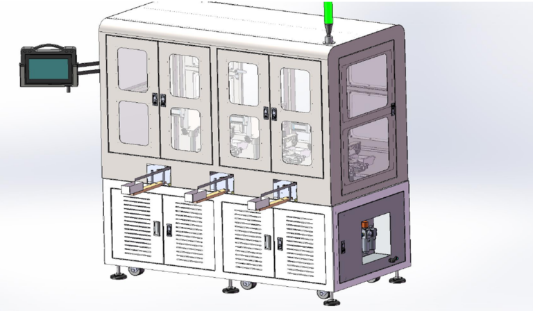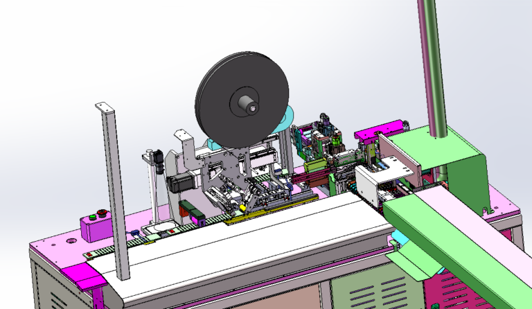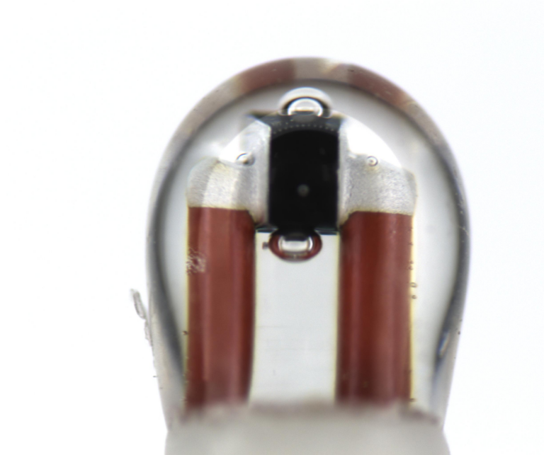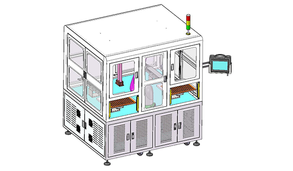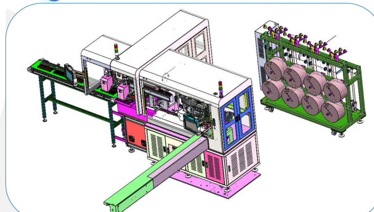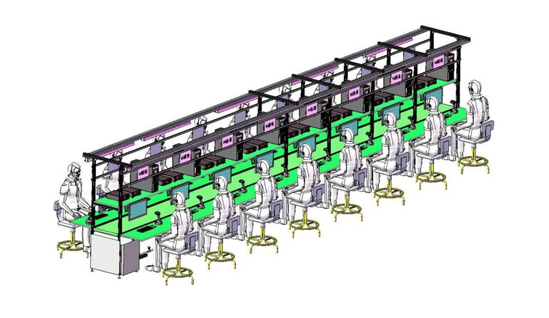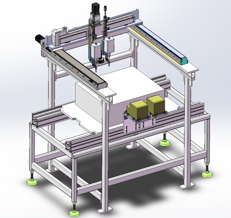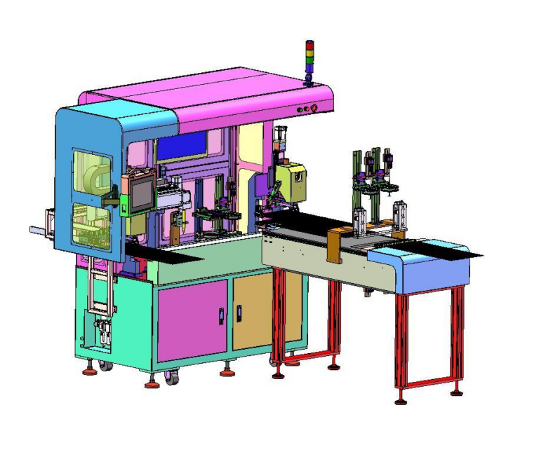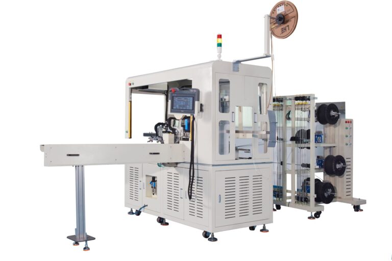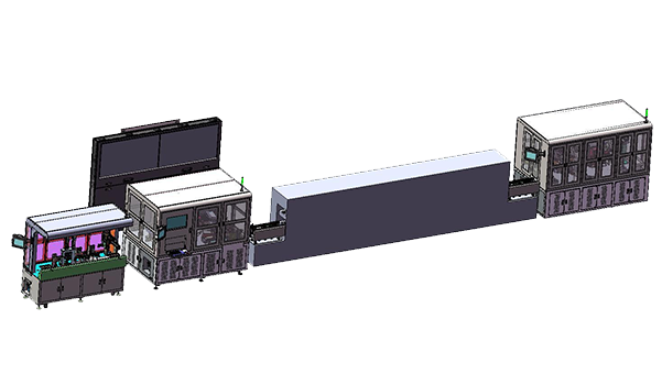
In this NTC sensor industry NTC water temperature sensor intelligent production line project, the production flow covers NTC welding, connector assembly, housing dispensing, O-ring assembly, high-temperature curing, riveting, laser marking, electrical testing, and final unloading. The planned line capacity is 240–260 pcs/hour, while manual NTC loading, material transfer, and some inspection tasks are retained. The reference staffing level is six operators.
The processes on this line do not operate on the same time scale. The welding section targets manual loading at no more than 5 seconds per piece, the front and rear assembly sections both target no more than 15 seconds per piece, while the middle of the process includes approximately 40 minutes of preheating and high-temperature curing. Keeping these processes connected requires more than individual machine speed; tray quantity, WIP capacity, process handoff, and the way product data moves with the physical product also need to be planned together.
Robotlyne’s NTC Sensor Production Automation follows a similar modular process approach, combining automation stations around Wire Processing, Welding, Inspection, Coating, Potting, Curing, and Testing.
Working Backward from 240–260 pcs/hour
The line target is 240–260 pcs/hour, which corresponds to an average main production takt of approximately:
13.8–15 seconds per piece
This range is closely aligned with the design target of ≤15 seconds per piece for the front and rear assembly sections.
The welding section is designed to operate faster.
In this section, an operator loads the NTC into the tray, with a loading target of:
≤5 seconds per piece
The equipment then automatically completes connector loading, pin crimping, DC welding, room-temperature resistance testing, weld vision inspection, and OK/NG sorting.
The higher processing capability in the welding area provides some margin for fluctuations in manual loading, vision judgment, and tray changeover.
This also shows that 240–260 pcs/hour is better treated as the output rate the entire line needs to sustain, rather than requiring every machine to operate at exactly the same PCS/H.
The Tray Starts Controlling the Process from the Welding Stage
The tray in this project is not used only to transport the product.
It needs to locate both the NTC wire and the connector. The NTC is constrained on both the connector-pin side and the outer side, while a clamping mechanism keeps the wire centered on the pin. A head stop is also used to control the final assembly length.
As a result, the downstream welding position is already mechanically constrained when the product enters the tray.
After the operator loads the NTC, DC Welding, vision inspection, and subsequent transfer do not handle a freely moving wire harness. They handle a semi-finished product whose relative position has already been established.
The tray also needs to consider future compatibility with other low-temperature sensor products.
The case also reserves space for future Automatic NTC Loading. Keeping manual NTC loading in the current phase does not change the overall sequence of Connector Feeding, Crimping, and Welding. If production volume increases later, an automatic loading module can be added on top of the existing process.
This approach is easier to control in terms of investment and implementation complexity than forcing every manual action into automation during the first phase.
Front Assembly Depends on Both Dispensing Quantity and Product Position
After welding, the product enters Front Assembly.
This section includes the Housing Tray, O-ring, Connector-NTC Assembly alignment, high-temperature adhesive dispensing, Inner O-ring assembly, insertion of the NTC into the Housing, and transfer to the High-Temperature Tray.
The cycle target for this workstation is:
≤15 seconds per piece
One operator is assigned to the station.
The dispensing process needs to control both position and adhesive quantity.
The case uses a Pneumatic Syringe, AP-III Air-Pressure Controller, and Stainless Long Needle. After adhesive replacement, a Fiber-Based System automatically corrects the Needle Position, while a 3-axis M-control Controller manages the dispensing path and automatic needle alignment.
The needle is also cleaned on a lint-free cloth at a defined interval.
Adhesive quantity is monitored through Online Weighing. The product is weighed before and after dispensing, and the system generates an alarm when the adhesive quantity falls below the defined lower limit.
This means that even if the dispensing path executes correctly, the actual amount of adhesive can still be checked independently through weight change.
For this type of sensor assembly, confirming that the needle reached the correct position is not enough to confirm a valid dispensing process. Position, adhesive quantity, and needle condition can all affect downstream assembly and curing.
A 40-Minute Curing Process Changes the WIP Requirement of the Entire Line
After front assembly, the product enters the thermal process.
The curing profile defined in the case is:
80°C × 10 min Preheating
followed by:
150°C × 30 min Curing
Each product therefore remains in this stage for approximately:
40 minutes
Meanwhile, the front and rear mechanical assembly stations still operate at approximately 15 seconds per piece.
At the target output of 240–260 pcs/hour, a simple steady-state estimate indicates that approximately:
160–173 pieces
would be inside the preheating and curing process at the same time.
This figure does not yet include loading/unloading transitions or operating margin.
The curing section therefore needs enough High-Temperature Trays, oven capacity, and circulation space.
Front assembly can release one product approximately every 15 seconds, but those products do not leave the next process 15 seconds later. They remain inside the thermal system for tens of minutes.
If tray quantity or curing positions are insufficient, meeting the front-assembly cycle target will not help because WIP will eventually accumulate at the curing stage.
Capacity in this section is therefore better calculated from actual residence time and simultaneous product quantity rather than by assigning the oven a simple PCS/H figure.
Rear Assembly Connects Mechanical Processing with Product Identity
After curing, the product enters the rear section.
- Riveting
- Dot Marking
- Laser Marking
- Hipot Testing
- Room-Temperature Resistance Testing
- External O-ring Assembly
- Final Tray Unloading
A Six-Axis Robot transfers the product between these processes, and the cycle target is also controlled at:
≤15 seconds per piece
The riveting process uses a Spring-Compressed Connector and Servo-Cylinder Riveting Structure while monitoring:
Stroke + Displacement
After riveting, the product is laser marked and then moves into Hipot and Resistance Testing.
The case requires:
Resistance Data to correspond one-to-one with the Laser-Mark Sequence Number.
From the Laser Marking stage onward, the equipment is not only handling the physical product; it is also establishing product identity.
Downstream test results can be linked to a specific sequence number. If an individual product later needs to be traced, the test data can be associated with that specific item rather than only with a general production batch.
This design connects the Physical Product and Production Data within the same production flow.
The Test Station Also Needs Stable Reference Conditions
The Room-Temperature Resistance Check does not rely only on a fixed threshold inside the test equipment.
The case also includes a nearby:
Standard Sample
The product and the standard sample both need to reach a stable air temperature before Resistance Comparison, and the Standard Sample requires regular Calibration.
The project also plans an external high-temperature oil bath or water bath for Thermal Validation.
The daily control conditions for the test station therefore include more than the tester itself:
- Standard Sample condition
- Temperature stabilization time
- Calibration interval
- Test circuit
The Resistance Test in the case also considers a 4.02 kΩ Pull-Up Resistor.
Automated test equipment can repeat the measurement consistently, but long-term comparability also depends on the reference sample, temperature conditions, and calibration status being controlled together.
Where the Six Operators Remain in the Process
The case specifically states that:
Board-Level UPH decreases as feeder quantity increases.
This is worth paying attention to.
At first glance, adding more Feeders may seem like it should make the machine faster because:
more screws are available at the same time.
In practice, more Feeders often mean:
- more screw types on the product;
- more fastening positions;
- more screw pickup actions;
- longer X/Y/Z travel paths;
- more complex workload distribution between the two heads.
So:
More Feeders
often means:
More Fastening Work
and therefore a longer total cycle.
This means:
600–900 PCS UPH
should not be treated as one fixed value for every configuration.
Actual capacity needs to be calculated from:
Screw Quantity + Screw Type + Fastening Positions + Feeder Count + Motion Path
Why 900 UPH Should Not Be Used as a Universal Capacity Claim
The staffing reference in the case is:
6 Operators
On average:
3 operators are responsible for Machine Watching
and:
3 operators are responsible for Material Transfer and Inspection
The welding, front-assembly, and rear-assembly sections also retain operator participation.
Manual work is concentrated mainly in NTC Loading, machine monitoring, Material Transfer, and Inspection.
The automated equipment handles operations such as DC Welding, Crimping, Vision Inspection, Dispensing, Insertion, Riveting, Laser Marking, and Electrical Testing, where repeatability and process consistency are more important.
This division of work also leaves room for future upgrades.
For example, the welding area already reserves space for Automatic NTC Loading. If production volume, labor cost, or production methods change later, manual loading can be reduced without redesigning the entire line.
From ≤5 seconds per piece for welding-area loading, to ≤15 seconds per piece for front and rear assembly, and approximately 40 minutes for thermal processing, this automated Production Line operates across several very different process time scales. Sustaining 240–260 pcs/hour depends on tray circulation, curing capacity, equipment takt, and the test flow continuing to connect reliably.
If you are planning a new NTC Sensor automated Production Line, it is useful to define the product process, target capacity, tray positioning, curing WIP, and test traceability requirements before deciding the automation depth of each stage. Contact Robotlyne to discuss your NTC production-line requirements.