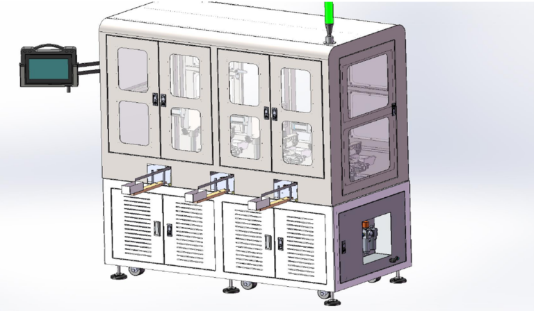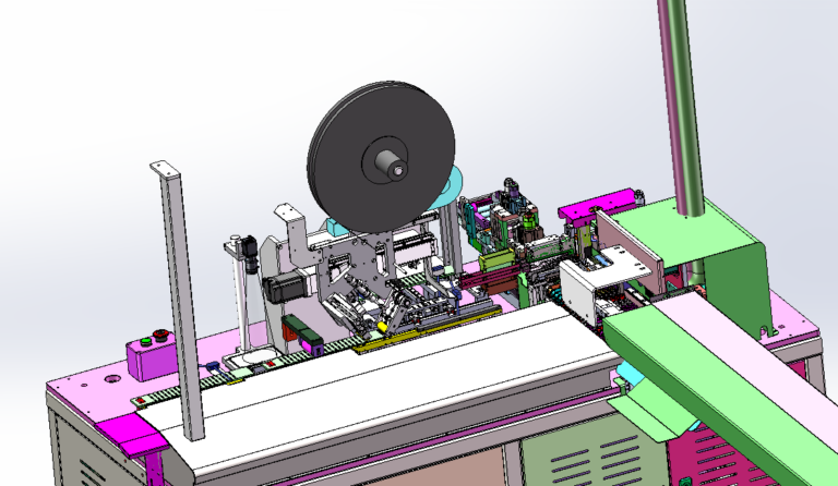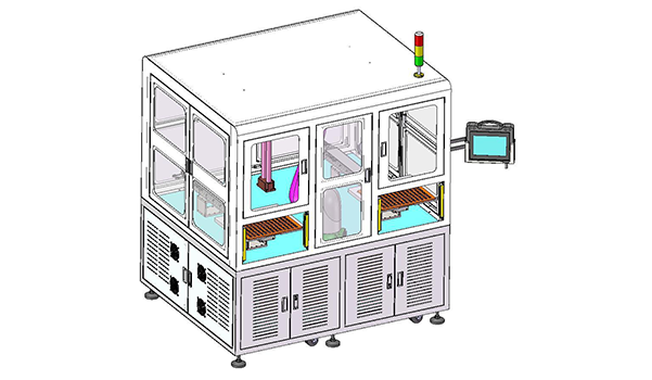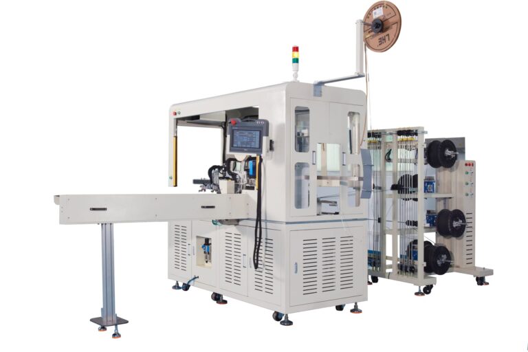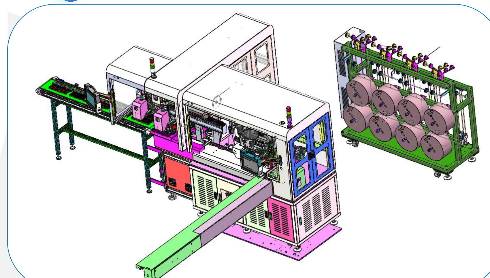
In this electronics industry wire carrier board resistance welding project, automated Welding does not begin with a wire that is already fully prepared. The machine needs to combine Wire Payoff, wire cutting, stripping, carrier board feeding, Tape Bonding, component lead cutting and forming, and Resistance Welding into one continuous process, while the entire welding flow is specifically designed without a Tinning step. The planned output is 1,000–1,200 pcs/h, with one operator supporting machine operation.
This “No Tinning” requirement changes the focus of the machine design. Exposed wire length, component lead geometry, carrier-board positioning, and the final contact condition at the weld point all need to remain stable before the product reaches the Welding Mechanism, because there is no additional tinning process later to compensate for variation in the upstream geometry.
Robotlyne’s Automated Welding & Soldering solutions also cover Resistance Welding, automatic feeding, component lead forming, welding, and integration with upstream and downstream processes, making this page more relevant to the project than a broader electronics automation page.
The Welding Process Actually Starts at Wire Payoff
The process flow in this case is:
Wire Payoff
↓
Wire Cutting
↓
Wire Stripping
↓
Carrier Board Feeding
↓
Tape Bonding
↓
Component Loading
↓
Lead Cutting and Forming
↓
Resistance Welding
↓
Conveyor Discharge
If only the final Resistance Welding step is treated as the core process, it is easy to overlook the fact that the earlier operations are already preparing the conditions for the weld.
Wire Cutting determines the wire length.
Wire Stripping determines the exposed conductor condition.
The Carrier Board determines the wire position as it enters the welding area.
Tape Bonding keeps the wire in that position while the board continues through the process.
Before the component reaches the Welding Section, its leads also need to be cut and formed.
By the time the Welding Mechanism starts, the relative geometry between the wire and the component has already been largely established.
The welding process therefore does not rely on correcting every deviation at the welding head. Much of the process stability comes from the upstream mechanical operations consistently presenting the product in a repeatable welding condition.
Without Tinning, Lead Forming Becomes Part of the Welding Condition
This project specifically modifies the component geometry before welding.
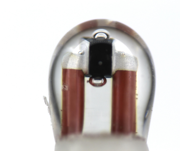
The public drawing includes forming dimensions such as 12 ± 0.5 mm, R0.65, R1.15, 14 mm, 15 mm, 17 ± 0.5 mm, and 4 mm. The case states that these forming changes are intended to make the downstream Welding Process simpler and more efficient.
This is important.
If a Tinning process were included, there would still be another material-preparation step before welding.
With direct Resistance Welding, the contact condition between the component lead and the wire depends more heavily on:
- Lead Shape
- Bend Radius
- Lead Length
- Wire Position
- Contact Area
The Cutting and Forming Module therefore cannot be treated as a routine upstream preparation machine.
It is already influencing the final Weld Joint.
If the formed component enters the welding area with inconsistent angle, dimensions, or contact position, the actual welding condition will vary even if the Welding Mechanism uses exactly the same parameters every cycle.
The Carrier Board Does More Than Transport the Product
This project uses Carrier Boards to carry the wire through the downstream processes.
Carrier Boards are automatically pushed out from a Magazine, then combined with the prepared wire through the Tape Unit before moving into component assembly and welding. The Magazine can store approximately 50 Carrier Boards.
The board performs two functions.
One is material transport.
The other is process positioning.
If the Carrier Board were only used for transportation, the wire could tolerate much greater positional variation on the board.
But the downstream process includes Resistance Welding, which means the wire cannot arrive at the Welding Mechanism in a completely random position.
Tape Bonding therefore does more than:
attach the wire to the board.
It needs to keep the wire in a usable position as the carrier continues through the machine.
The relationship becomes:
Carrier Board Position
↓
Wire Position
↓
Component-to-Wire Welding Position
This is why Carrier Board Handling and Automated Welding cannot be treated as two separate projects in this application.
A 2–8 Roll Wire Payoff Configuration Requires Flexible Front-End Feeding
The Payoff Rack in this project can be adjusted according to the application, with a configuration range of:
2–8 Wire Rolls
This means the front-end wire supply is not a fixed structure.
If the product requires only a small number of wire rolls, the machine can use a simpler feeding configuration.
As product variants or production recipes increase, the Payoff Rack needs additional space for more Wire Rolls and for roll replacement.
This affects:
- Wire Routing
- Rack Footprint
- roll changeover
- Wire Identification
- interference control between multiple wire rolls
The overall machine layout therefore cannot be compressed only around the Welding Head.
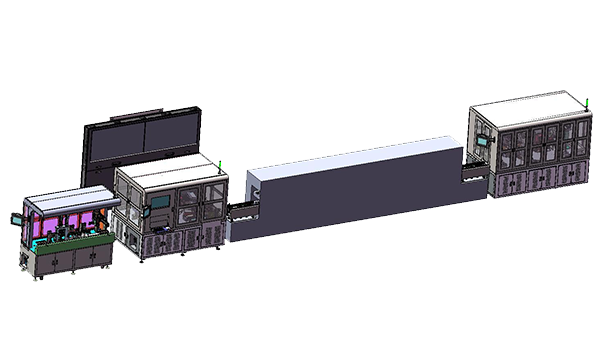
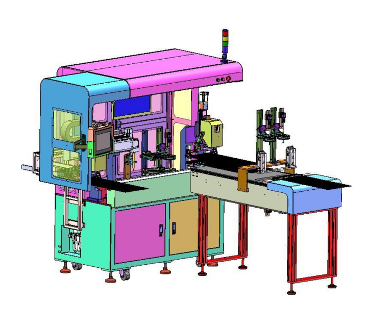
The layout shown in the case needs to accommodate the Payoff Rack, Wire Inlet, Wire Arranging Path, Cutting / Stripping section, Carrier Board Magazine, Tape Unit, Component Magnetic Box, Forming Mechanism, and Welding Mechanism along the same process direction.
The Full Process Has to Sustain 1,000–1,200 pcs/h
The planned machine output is:
1,000–1,200 pcs/h
with:
1 Operator
and an:
HMI + PLC
control system.
This capacity should not be interpreted simply as the Welding Mechanism performing 1,200 welds per hour.
Before a product leaves the machine, it has already passed through Wire Payoff, Cutting, Stripping, Board Feeding, Tape Bonding, Component Feeding, Lead Forming, Welding, and Conveyor Discharge.
A sustained delay in any one of these steps will reduce the final machine output.
For example:
If the Carrier Board Magazine does not feed boards reliably, the Welding Section will run out of material.
If Wire Cutting / Stripping cannot maintain the required pace, the downstream process will also wait.
If the Component Magnetic Box or Forming Mechanism stops, prepared Wire Boards will begin to accumulate upstream.
The 1,000–1,200 pcs/h figure is therefore better understood as the planned capacity of the complete Machine Flow rather than the isolated speed of one actuator.
One Operator Manages the Conditions for Continuous Operation
The case specifies:
1 operator
This does not mean the machine operates without human involvement.
The operator still needs to monitor:
- Wire Roll supply
- Carrier Board Magazine
- Component Supply
- Tape Material
- Alarms
- fault recovery
- Finished Assembly Discharge
Automation places many repetitive actions inside the machine, while the operator ensures that the required input conditions remain available and handles abnormal conditions.
For an integrated machine like this, the more process modules that are connected, the less the operator is managing one individual station. The operator is managing whether the entire continuous process remains ready to run.
Utility Conditions Also Affect Welding Stability
The case specifies:
AC380V
and:
0.5–0.7 MPa Air Supply
Compressed air may be used for positioning, clamping, feeding, or other auxiliary mechanisms.
If plant air pressure fluctuates significantly, the first symptom may not appear as an incorrect welding parameter. It may appear as:
- unstable Component Feeding
- changes in positioning time
- abnormal cylinder motion
- material not reaching the expected position
These mechanical variations can eventually be transferred into the Welding Section.
Commissioning therefore cannot focus only on Welding Current or Welding Time. The complete machine also needs to perform consistently under the actual plant Utility conditions.
The Main Goal Is to Present a Repeatable Product Condition Before Welding
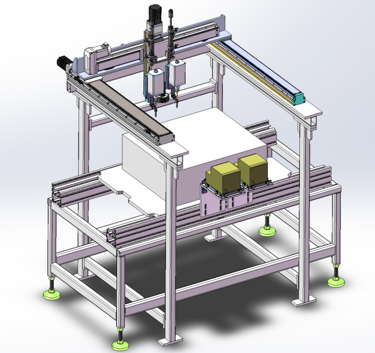
Looking at the equipment list, this project includes a Payoff Rack, Carrier-Board Machine, Tape Unit, Component Magnetic Box, Cutting and Forming Mechanism, Resistance Welding Mechanism, and Discharge Conveyor.
These modules are not included simply to make the machine more complete.
They are arranged around one continuous objective.
The wire must first be cut and stripped accurately.
The Carrier Board must bring the wire into a defined position.
The Tape Unit must maintain that position.
The Component Lead must be formed into a geometry suitable for welding.
Only then does Resistance Welding create the final connection under those prepared conditions.
That is what makes this electronics industry automated Welding project distinctive. Once Tinning is removed, weld quality depends more heavily on consistent upstream geometry preparation and Material Handling, so the preprocessing, carrier system, and Welding Mechanism need to be designed as one continuous machine.
If your electronics product also involves Resistance Welding, Wire Preparation, Lead Forming, or Carrier-Based Assembly, the equipment boundary can be defined by starting with product geometry, welding contact requirements, wire-length range, and target throughput. Contact Robotlyne to discuss your Automated Welding project.