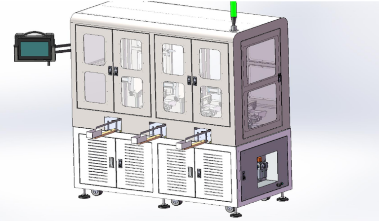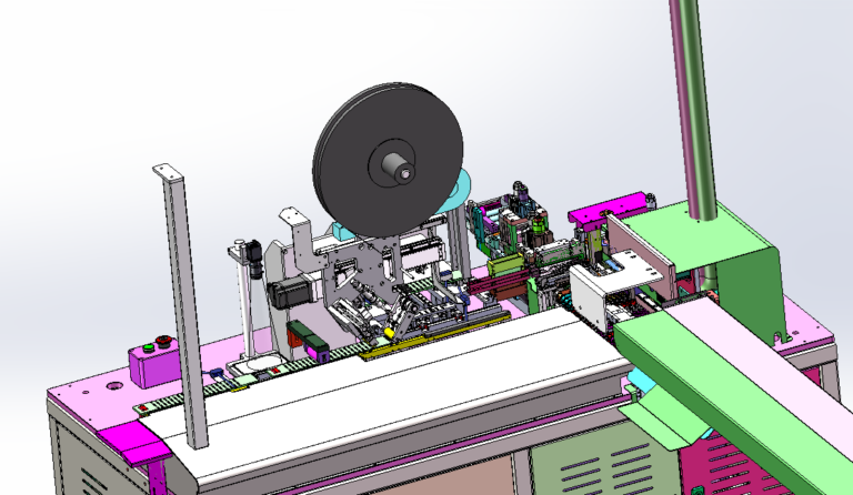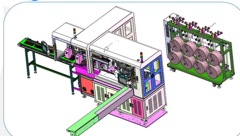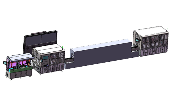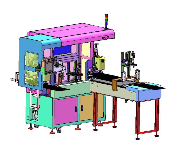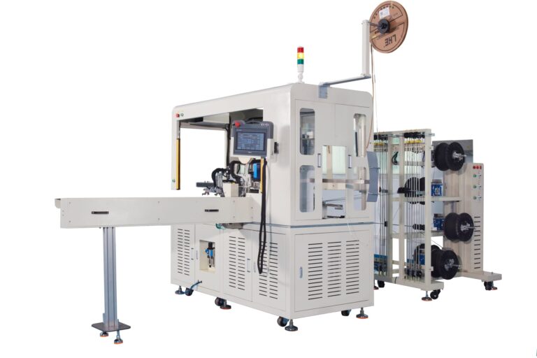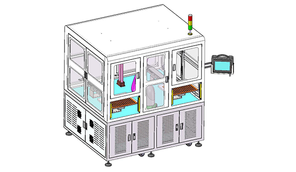
In CNC manufacturing, Machine Tending often sits between machining and the next production step. This Robot Loading and Unloading Laser Marking Machine uses trays as the handoff point between the operator and the automated cell. The operator loads parts at Manual Station A or B. Once a tray enters the machine, a six-axis robot picks each part, moves it to the Laser Marking Station, performs 2-3 marking orientations, and returns the finished part to the tray. The machine is rated at 500-600 PCS/H with one operator.
The equipment list itself is relatively compact: Tray Transfer, Six-Axis Robot, Pneumatic Gripper, and Laser Marking Module. The more important part of the design is what happens to the workpiece after the robot lifts it from the tray. A single gripping point has to remain usable while the product changes orientation several times, moves through the laser process, and finally returns to a tray-compatible position.
Robotlyne’s Custom Assembly Automation covers robotic workstations, automated handling, and the integration of multiple processes into one cell, which is relevant to this type of tray-based Machine Tending application.
One Pickup Has to Support Several Marking Orientations
The operator first places parts into a tray at Manual Station A or B.
Tray Transfer then moves the loaded tray into the Robot Pickup Position. The six-axis robot grips the first part and transfers it to the Laser Marking Station.
For a single-surface marking process, the movement could be relatively direct:
Tray
↓
Laser Marking
↓
Tray
This project adds another layer.
After the first marking operation, the robot changes the workpiece orientation and presents another surface to the laser. Some products require a third orientation before the part can be returned.
The gripping point therefore has to work through the complete sequence:
Pickup
↓
First Marking Orientation
↓
Second Orientation
↓
Possible Third Orientation
↓
Return Orientation
↓
Tray Placement
A gripper position that works well for the first surface may obstruct another marking area after the part rotates.
The workpiece also changes its relationship with gravity as the robot wrist turns. A part held securely in one orientation still has to remain stable while the robot moves through the next marking position.
The usable robot path is therefore defined by several physical relationships at the same time:
- the part geometry;
- the Pneumatic Gripper and finger position;
- the laser access area;
- the required marking faces;
- the surrounding machine structure;
- the final orientation required for tray return.
The tray remains the robot’s starting and finishing reference. Once the workpiece leaves that reference, the robot and EOAT have to maintain control through every intermediate orientation until the part is placed back.
This makes the cell closer to a short robotic processing sequence than a basic Point-A-to-Point-B transfer.
500-600 PCS/H Is Built from the Entire Part Movement
The machine capacity is 500-600 PCS/H, equivalent to an average output interval of roughly 6-7.2 seconds per part.
That time includes much more than the initial pickup.
A complete part movement contains several actions:
Tray Pickup
↓
Move to Laser Station
↓
First Marking
↓
Reorientation
↓
Second Marking
↓
Additional Orientation if Required
↓
Return Rotation
↓
Tray Placement
Tray movement also has to support the robot cycle before the next part can be processed.
Multi-orientation marking changes the character of the cell because the robot is not repeatedly executing one identical transfer path. Each additional marking face inserts another rotation, clearance movement, and laser presentation into the same handling cycle.
Robot Path design therefore affects production rate directly.
A compact rotation between two marking faces keeps the sequence short. A larger reorientation may require the robot to move away from the laser head, clear the surrounding structure, rotate the part, and then approach the next marking position again.
The gripper affects the same sequence. If the EOAT blocks a marking surface or forces the robot to use a longer clearance path, the effect appears repeatedly on every part.
At 500-600 PCS/H, these small movements accumulate across hundreds of cycles.
That makes Gripper Geometry, Wrist Motion, Marking Position, and Tray Position part of the same cycle-design problem rather than separate equipment specifications.
Connecting the Same Part Flow to a CNC Machine
The current cell begins and ends with a tray.
The operator loads the tray, the robot processes the part through multiple Laser Marking orientations, and the finished part returns to the same material-handling format.
A CNC-connected version changes the beginning of that sequence.
Instead of:
Tray
↓
Robot
↓
Laser
↓
Tray
the material path may become:
CNC
↓
Robot
↓
Laser
↓
Tray
or:
CNC
↓
Robot
↓
Laser
↓
Next Process
The robot now has to interact with the machining process before it reaches the marking station.
The workpiece leaves the CNC in the orientation defined by the machine Chuck or Fixture. From there, the robot has to establish a secure grip, clear the machine enclosure, move toward Laser Marking, and begin the same multi-orientation sequence used in the standalone cell.
If the part needs cleaning, inspection, or an additional flip between machining and marking, those operations become additional robot destinations within the same material path.
This changes how Robot Reach and EOAT should be considered.
Reach is no longer defined only by the distance between Tray and Laser Station. It now includes the CNC Loading Position, machine access envelope, marking positions, and final discharge point.
The EOAT also has to work with both the CNC handoff geometry and the multiple laser-marking orientations.
A gripping area that is convenient for unloading the CNC still has to leave the required marking surfaces accessible afterward.
The robot therefore carries the same workpiece through several different mechanical interfaces:
CNC Fixture
↓
Robot Gripper
↓
Laser Marking Positions
↓
Tray / Downstream Handoff
That continuity is the main connection between Machine Tending and the original Laser Marking Cell.
The automation is built around one part remaining under controlled handling while its orientation and processing location change several times.
For CNC manufacturing projects that need to connect machine unloading with multi-orientation Laser Marking, contact Robotlyne to discuss the workpiece handoff, EOAT, robot path, and downstream material flow.