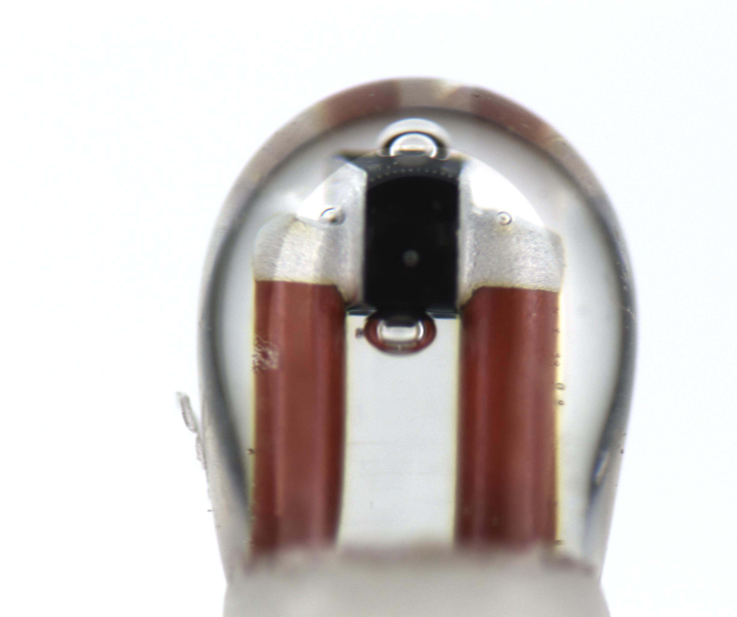
In NTC sensor production, designing an automated optical inspection machine does not usually begin with selecting a higher-resolution camera. In this Single-End Component AI Visual Inspection Lighting case, real single-end component defect samples were first used for Lighting Validation and an AI Appearance Inspection Feasibility Review. The purpose was to confirm whether six defect types—Short Dimension, Single Wire, Ceramic-Tube Separation, Internal Contamination, Darkened Lead Wire, and Chip Detachment—could form sufficiently stable and distinguishable visual features under machine-vision conditions. The target equipment efficiency is 2,500 PCS/H, with a visual defect accuracy requirement of 20 μm.
This validation step takes place before the complete mechanical design of the inspection machine. The reason is straightforward: if a certain defect still cannot be presented consistently under suitable lighting, viewing angle, and imaging conditions, adding more cameras, designing a feeding mechanism, or increasing mechanical throughput later will not automatically solve the inspection problem. By first placing real samples under the vision system, the project can identify what can be detected, what may be misclassified, and where the remaining risks are. Camera Placement, Lighting, Station Layout, and the AI Model then have clearer design inputs.
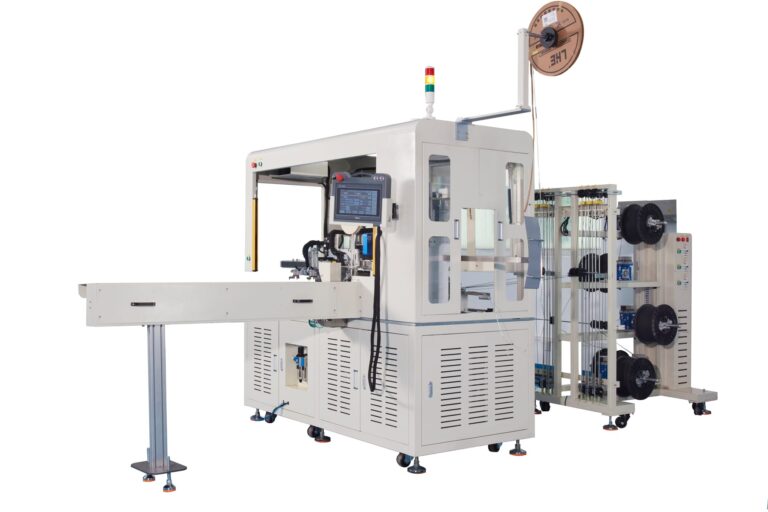
Robotlyne’s NTC Sensor Production Automation also includes CCD Vision Inspection and AI Recognition for NTC semi-finished products and welding quality, helping identify wire-spacing abnormalities, welding misalignment, and other visible defects while retaining inspection data.
Before Designing the Inspection Machine, First Make the Six Defect Types Visible in the Image
The samples used in this project are not simply six visually similar NG products. The causes of the defects are different.
Short Dimension and Single Wire are closer to geometric-state abnormalities. The vision system needs to evaluate product length, the number of wires, or their relative positions.
Ceramic-Tube Separation and Chip Detachment involve changes in the assembly relationship. Structures that should normally remain connected have separated, or an internal component has moved away from its intended position.
The other two defects—Internal Contamination and Darkened Lead Wire—are more closely related to changes in appearance, color, or visible internal areas.
An experienced human inspector may identify these defects quickly when looking directly at the part. A machine, however, sees only an image.
A metal lead may produce reflections. Transparent or semi-transparent packaging can superimpose internal structures, surface reflections, and the background in the same image. Structures at different depths may also be affected by depth of field.
The first question in sample validation is therefore not simply:
Can AI recognize the defect?
The more fundamental question is:
Does the captured image show a sufficiently stable difference between the normal area and the defect area?
If the lighting causes a metallic reflection to cover the color difference associated with a Darkened Lead Wire, the AI model will still be working from an image that lacks useful information.
If Internal Contamination overlaps with normal internal structures from the current viewing angle, increasing the number of training samples may not resolve a problem that originates in the imaging condition itself.
This is why the project begins with Lighting Validation.
The current case conclusion is that the six known defect types can be detected for the samples provided. However, this conclusion applies only to the validated Sample Set. If new defect types appear later, they still need to be evaluated separately rather than being assumed to fall within the existing inspection capability.
This boundary is important for later AOI Equipment Acceptance.
The supplier and customer need to know whether the acceptance scope means:
all possible appearance defects
or:
the specific Defect Classes that both sides have defined and validated
The latter can be converted into an executable inspection standard.
Why a Small NTC Component Still Needs Top and Surrounding Views
Once the sample validation is complete, the inspection-station concept becomes more concrete.
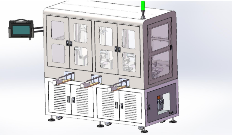
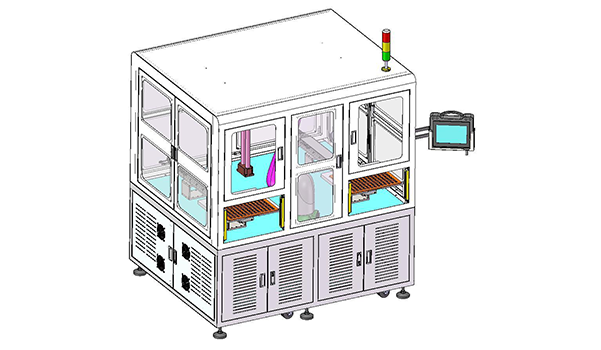
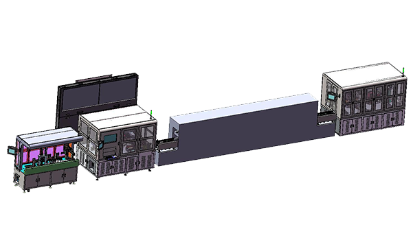
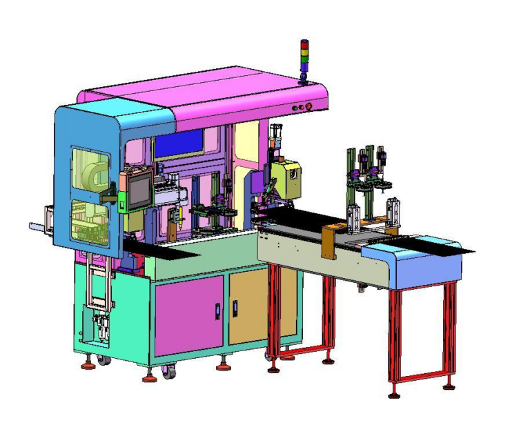
The case plans three Inspection Stations, including one Top Inspection Station and Surrounding Inspection Stations for the external surfaces.
This arrangement is not intended simply to increase the number of cameras.
The reason can be understood from the product geometry itself.
If Short Dimension or certain top-side structures are most clearly captured from directly above, a Top View provides a stable measurement direction.
However, the ceramic tube, lead wire, chip, and encapsulated body also include side structures. When a defect occurs around the perimeter of the part, a top image may show only a projection rather than the actual defect location.
The same component therefore needs visual information from multiple directions.
This is also one reason the case specifically identifies Bottom Crack as a remaining risk.
The current evaluation indicates that cracks located at the bottom may still carry a missed-detection risk. Very small dents, such as those below approximately 5 μm, are also listed as potential risks.
At this point, an easy assumption is:
If there is a risk, just add another camera.
In practice, the design is not that simple.
Adding another viewing direction also adds:
- Camera / Optics
- Lighting Position
- Trigger
- Image Acquisition Time
- Data Processing
- Mechanical Space
- Calibration Work
The project still needs to meet a target of 2,500 PCS/H.
The final inspection machine therefore cannot add unlimited viewing angles in pursuit of theoretical coverage of every possible surface. The required views need to be selected according to where the defects occur and what the acceptance criteria require, while some issues may remain as identified risks or may require an additional mechanism to change the product orientation.
The current concept uses Top + Surrounding Inspection, with the six known defect types first mapped to viewing directions that can present them effectively before the complete equipment design is finalized.
From “The Sample Can Be Recognized” to 2,500 PCS/H, There Is Still a Full Equipment-Engineering Step
Lighting Validation shows that the current Sample Defects can be presented visually, but this is not yet a complete production AOI machine.
The downstream target conditions are already relatively clear.
Target equipment efficiency:
2,500 PCS/H
Visual defect accuracy:
20 μm
Missed Detection Target for Major Defects:
0%
The Overkill target is not a single fixed number. It varies with incoming yield:
- When Incoming Yield is above 96%, the Overkill Target is ≤3%.
- When Incoming Yield is 90%–96%, the Overkill Target is ≤5%.
There is an important design relationship here.
If the only priority is reducing missed detection, the simplest approach is often to make the classification threshold extremely strict.
But the stricter the threshold becomes, the more likely normal products are to be classified as NG.
As Missed Detection decreases, Overkill can increase quickly.
At 2,500 PCS/H, that kind of false rejection can become a real production problem. Even if the vision system does not allow defective parts to pass, a large number of OK parts entering the Reject Flow would still create additional manual review, product handling, and data work.
For this reason, the project starts defining both Defect Visibility and the Detection Boundary during the sample stage.
Internal Contamination is a good example. The presence of any internal color change does not automatically mean the product should be rejected.
The case specifically notes that the Inspection Range for this defect still needs to be defined in order to avoid over-rejection.
This directly affects AI Training.
Before training the model, the product acceptance rules need to be clear:
- Where does contamination count as NG?
- How large must the affected area be before it is judged NG?
- At what color or grayscale change does the condition become abnormal?
- Who confirms the boundary samples?
If these conditions are not aligned first, the AI model may simply move the same human disagreement into software.
The current case confirms the use of AI Inspection: sample images are used for training, and the trained Network Weight Table is then used for Neural-Network-Based Detection. Final model qualification, however, still needs to be confirmed at the complete equipment stage.
Moving from the current Feasibility Study to a production-ready automated optical inspection machine therefore still requires the validated visual conditions to be translated into actual equipment parameters:
Where should each camera look?
How should the Lighting be fixed?
How should products move through the three Inspection Stations?
At 2,500 PCS/H, how much imaging and inference time is available per part?
How should new Defect Samples enter the validation process?
Should Bottom Crack and dents below approximately 5 μm be included in acceptance, treated as known risks, or addressed with an additional inspection method?
Once these conditions are defined, Mechanical Design, Camera Placement, and AI Model Qualification can be frozen with much clearer boundaries.
This is the most useful point in this NTC sensor case: the first step in Automated Optical Inspection is not to design the machine itself, but to validate which defects can be seen reliably and under what conditions. The current project has already established six known defect classes, a 2,500 PCS/H target, a 20 μm accuracy requirement, a Top + Surrounding Inspection concept, and several remaining inspection risks, providing the boundaries for the next stage of complete equipment design.
If you are planning NTC Sensor appearance inspection, weld inspection, or AI Vision Inspection, it is useful to begin with real OK/NG samples to build a Defect Library and complete Lighting Validation before defining cameras, inspection stations, and equipment takt. Contact Robotlyne to further evaluate the inspection scope, sample conditions, and implementation of an automated optical inspection machine.