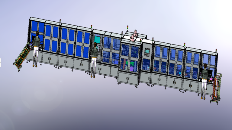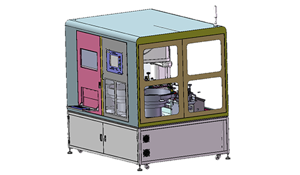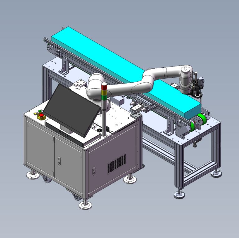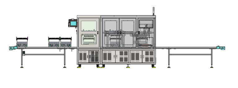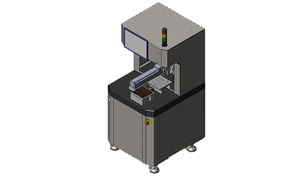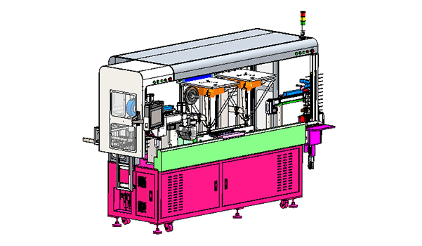
In Wire Harness and Sensor manufacturing, automated assembly equipment sometimes has to handle two materials with completely different mechanical behavior. In this Automatic Wire-Board Loading Cell case, one side of the cell handles a Wire Board with fixed geometry, while the other handles loose Wire Harnesses whose orientation keeps changing after vibration and belt feeding. The machine brings these two material flows together, then uses CCD-Guided Dual Spider Robots, Tape Application, and Wire Alignment to turn a single Pick-and-Place action into a stable Board Arrangement. The test product uses 40 Wire Harnesses, with 2 wires sharing each Slot, a 13 mm Board-Center Interval, and a planned average efficiency of 1,800–2,000 products/hour.
The logic of the cell is straightforward: the Board first provides a fixed reference. Harness Feeding then continuously presents flexible wires to the Robot. The CCD and Spider Robots handle the Harnesses that are currently suitable for picking, while material with unsuitable posture enters the Return Flow. After the wires are placed on the Board, Tape and Alignment continue to hold them in positions that remain stable during downstream handling.
Robotlyne’s Electronics Assembly Automation covers automated part handling, loading / unloading, multi-operation processing, and vision-guided robotic workcells, making it relevant to applications that integrate flexible wire handling, vision guidance, and carrier-board assembly in one cell.
The Board Is Fixed; the Wire Harness Is What Keeps Changing
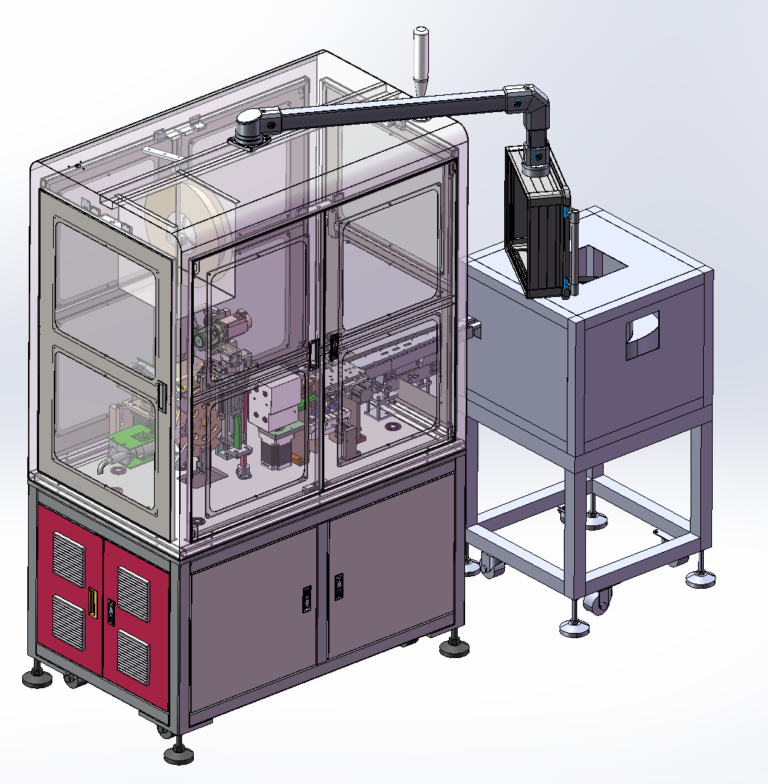
The empty Wire Board first enters the machine from a Magazine. The Automatic Board-Feeding Module uses a Board Magazine, Pickup Gripper, Lift Slide Cylinder, Transverse Module, and Ejector Module to remove the Board and send it to the Board Receiving Module. The Receiving Module then uses a Linear-Motor Module, Clamping Cylinder, and Receiving Tray to hold the Board in the position required for downstream assembly.
At this point, the target reference on the robot side has largely been established. The Wire Harness does not have the same stability.
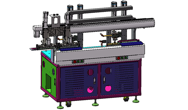
Harnesses enter through Rotary Feeding and a Vibration Feeder before reaching the Upper Flat Feeding Belt. A Lower Return Belt is installed below. Because the loose wires are flexible, the feeding system can keep material moving forward without making every Harness arrive at the Robot Pickup Area in exactly the same direction and posture.
Board: Fixed Receiving Position
Wire Harness: Variable Presentation
The cell uses two Spider Robots together with CCD Vision and Wire-Gripping Pneumatic Claws. The CCD primarily supports robotic handling in this application. The Robot responds to the current condition of the Harness, picks it, and places it onto a Board Layout that has already been fixed.
Vision therefore participates directly in Material Handling. It helps the machine identify Harnesses that fit the defined board-loading process, while the stable Board position gives the Robot a repeatable placement target. Both conditions support the 40-Wire Arrangement.
Not Every Harness Is Worth Correcting with the Robot
Once the Board has been fixed by the Receiving Module, Wire Harness posture remains the main source of variation. Vibration and Belt Feeding keep material moving, while the vision-guided handling sequence separates Harnesses that fit the current Pick-and-Place condition from those that do not.
The cell includes a Lower Return Line. When the Harness posture is unsuitable for the current Placement process, the material enters the lower return path and can periodically move into the NG Box instead of forcing the Spider Robot to correct every abnormal orientation.
This creates a clear mechanical boundary for the Robot Cycle.
Suitable Harness → CCD-Guided Pickup → Board Placement
Unsuitable Harness → Return / NG Flow
Keeping abnormal postures out of the main cycle reduces the number of special Robot Motions needed around the normal loading sequence. CCD Guidance, Wire Gripping, and the Lower Return Flow therefore work together as one Harness Handling logic.
The Robot Placement process now has a clear start and end point: the start is a Harness that can be handled reliably under the current vision condition, and the end is the Wire Board already fixed in the Receiving Position. Once the Harness reaches the Board, the process still continues.
A Successful Pick-and-Place Is Still Not a Finished Wire Board
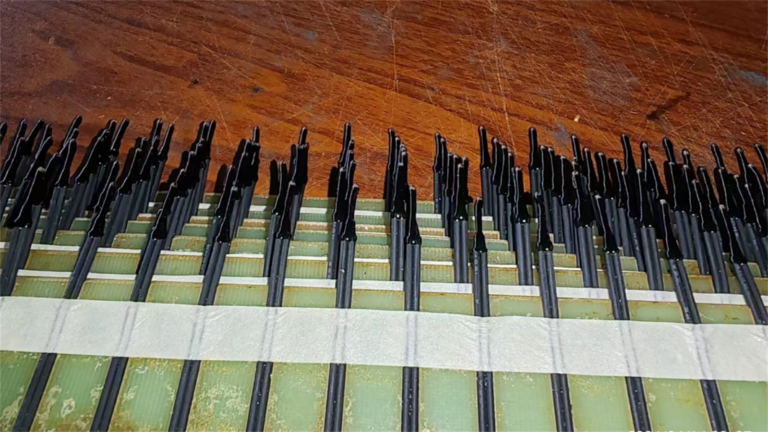
When a rigid component enters a locating pocket, the Fixture itself can usually prevent further movement. A Wire Harness behaves differently. The Spider Robot can place the Wire in the correct area, but after the Robot releases it, the flexible wire can still shift because of its own tension, Board Movement, or downstream handling.
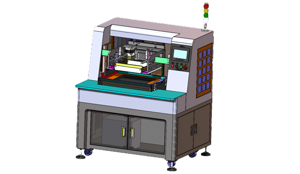
The case therefore continues with Tape Application and Wire Alignment. The Tape Application Module uses Tape, a Pressing Cylinder, Scissors, and Transverse Movement to secure the Harnesses that have already been placed on the Board. The Wire-Aligning Module then uses Aligning Grippers, Transverse Movement, and a Lift Module to organize the wires.
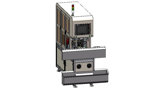
After these steps are complete, the Discharge Module uses a Board-Clamping Pneumatic Claw, Turnover Cylinder, and Transverse Module to move the Finished Board out for manual removal.
Vision-Guided Pickup → Placement → Tape Fixing → Wire Alignment → Finished-Board Discharge
The Spider Robot determines how the Wire reaches the target area on the Board. Tape keeps the Wire in that area after release. Alignment establishes the stable final arrangement. At this stage, 40 Wire Harnesses, 2 wires per Slot, and the 13 mm Board-Center Interval become a repeatable Board Layout.
The machine is a dedicated solution for one Board Specification / Layout. The confirmed 1,800–2,000 products/hour efficiency is therefore tied to the current Board Geometry, Harness Arrangement, Robot Placement, Tape, and Alignment conditions. A future product with a different Slot Pitch, Board Layout, or Harness Arrangement may require corresponding changes to Board Receiving Position, Robot Placement Coordinates, Tape Position, and Alignment Tooling.
If a Wire Harness or Sensor product still relies on operators to arrange large numbers of flexible wires one by one onto a Board, Tray, or Fixture, contact Robotlyne to discuss an automated cell combining Feeding, Vision, Robot Placement, and Wire Fixing.