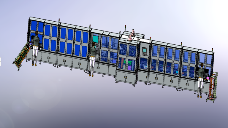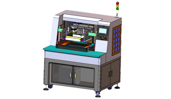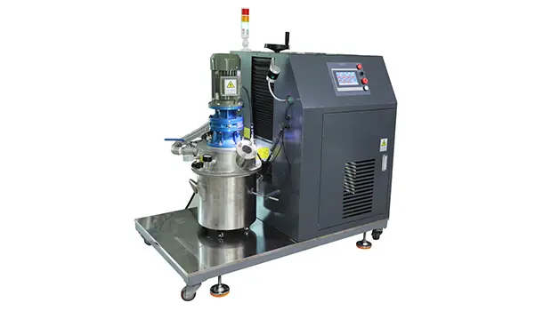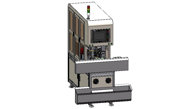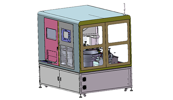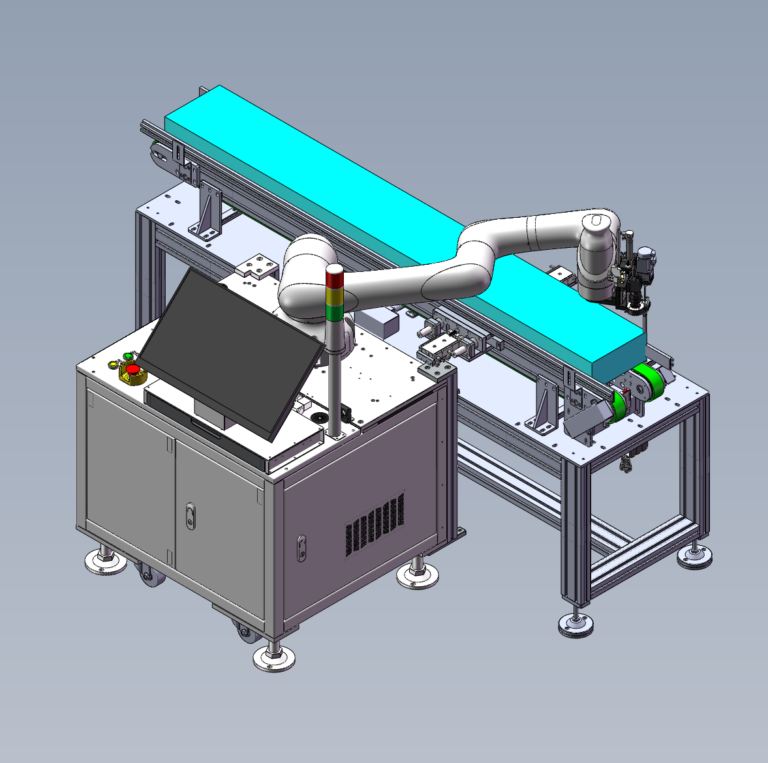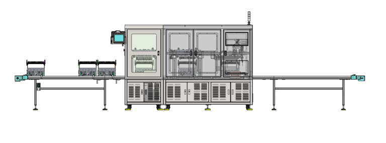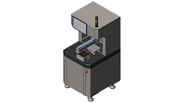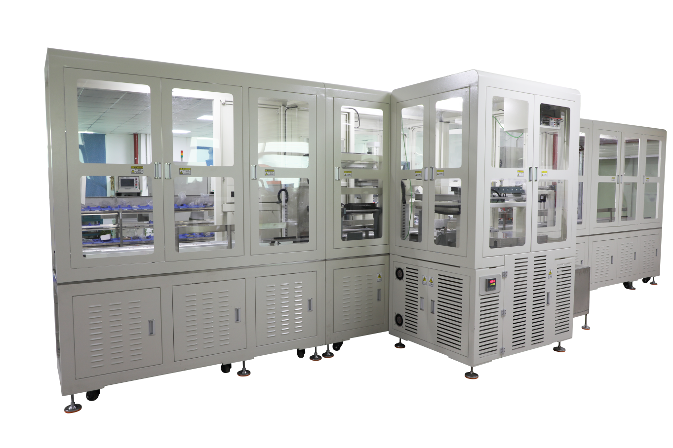
In NTC Sensor manufacturing, an Automated Production Line often includes Wire Cutting, Boarding, Resistor Forming, Welding, Encapsulation, Shell Insertion, Dispensing, and Final Testing. In this NTC Production Line with Process Fixtures project, Robotlyne planned a production line for 58-ohm resistor-based sensor assemblies with a target of approximately 20,000 pcs/day. The project uses 2,000 Line Boards, 120 Encapsulation Frames, 10 Turnover Carts, and approximately 150 sets of Potting Fixtures. These tooling systems are not duplicates; each one corresponds to a different mechanical state and transfer requirement at a different production stage.
At the front end, the Wire and Resistor have to maintain a precise positional relationship. During Encapsulation, batches of semi-finished parts are handled together. Once Shell Insertion and Dispensing begin, the product has to enter the Housing in a different orientation. Final Testing then shifts the production interface toward Hipot, 25°C / 85°C Resistance Measurement, Data Capture, and NG Separation. The line therefore does not keep one Fixture with the product from beginning to end. Instead, different fixture systems take over at different process interfaces.
Robotlyne’s NTC Sensor Production Automation covers Wire Processing, Forming, Lead Cutting, Soldering, Encapsulation, Potting, Curing, and Testing, and allows individual stations to be connected into a complete NTC Sensor Automated Production Line.
The 2,000 Line Boards First Establish the Wire-to-Resistor Relationship
The production line begins with Wire Cutting and Boarding.
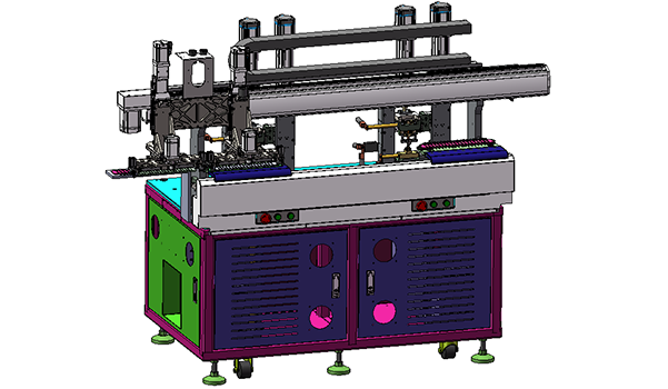
This section uses 8 Wire-Feeding Shafts. During production, five wire reels can be loaded at the same time, supporting a Wire-Length Range of approximately 50–1,500 mm. Feeding, Cutting, Stripping, Fluxing, Tinning, and Board Loading are organized continuously in the front-end equipment, with a planned capacity of approximately 1,800–2,000 pcs/hour.
The product then enters Dual-Station Resistor Forming, Lead Cutting, and Welding, with a planned capacity of approximately 1,600–2,000 pcs/hour.
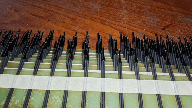
Across these two stages, the Line Board provides a specific mechanical function.
After the Wire is cut and processed, it cannot enter the next Welding stage in a completely free state. The Resistor also has to align with the prepared Wire Position during forming, lead cutting, and joining.
The front-end sequence therefore becomes:
Wire Preparation
↓
Board Loading
↓
Resistor Forming / Lead Cutting
↓
Dual-Station Welding
These operations use the Line Board to maintain a continuous positional relationship.
Robotlyne planned 2,000 Line Boards for the approximately 20,000-piece daily production target:
1,000 boards for the daily active requirement
1,000 boards to cover the downstream return cycle
At the front end, the Line Board acts as a moving reference. It carries multiple prepared Wires from the Feeding Machine into the Welding Section so the downstream equipment can continue working around established Wire Positions.
Once the product enters Encapsulation, the way it is mechanically organized begins to change.
At Encapsulation, the Same Products Are Reorganized into Frames
The front-end process is organized mainly around individual Wire / Resistor Assemblies and Line Boards.
The Encapsulation Machine has a planned capacity of approximately 10,000–14,000 pcs/hour.
For this stage, Robotlyne configured:
120 Encapsulation Frames
and:
10 Turnover Carts
Each Encapsulation Frame holds:
15 Fixtures
Each Fixture holds:
20 Parts
So one complete Frame corresponds to:
300 Parts
At this point, the mechanical organization of the NTC Semi-Finished Products is different from the front end.
The earlier relationship is:
Wire ↔ Line Board ↔ Welding Position
During Encapsulation, the production unit becomes:
20 Parts
↓
1 Fixture
↓
15 Fixtures
↓
1 Encapsulation Frame
After Welding, the product moves from the front-end positional reference into a new batch-fixture system.
The Frames carry the products through Encapsulation and downstream transfer, while the 10 Turnover Carts support movement between production areas.
This handoff allows the front-end Line Boards to return to their own circulation while the Encapsulation Section continues with a fixture format better suited to batch handling.
Instead of asking one Line Board to serve Welding, Encapsulation, Curing, and downstream assembly at the same time, each process stage uses the fixture format that matches its own product state.
Shell Insertion Introduces a Third Fixture Relationship
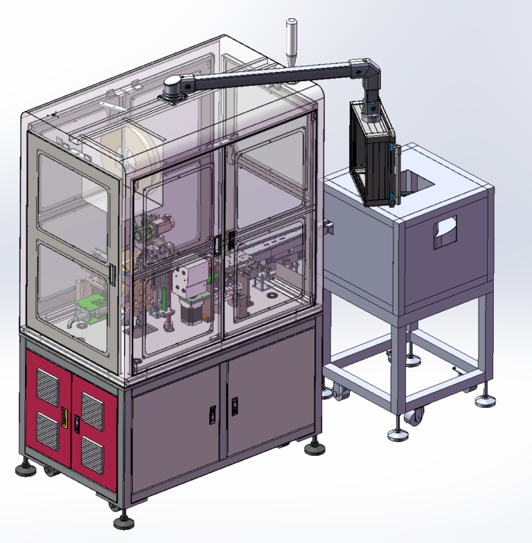
After Encapsulation, the NTC Sensor continues into Shell Insertion and Dispensing.
This section uses:
2 Vibratory Bowls
and:
4 Dispensing Heads
The planned production capacity is approximately 4,000–5,000 pcs/hour.
Robotlyne planned approximately:
150 Potting Fixtures
with each Fixture Set corresponding to approximately:
300 Parts
Another Fixture Handoff occurs at this stage.
The product is no longer only a Wire-and-Resistor assembly. Once the Shell enters the process, the equipment has to control several relationships at the same time:
- Sensor Body Position
- Shell Position
- Insertion Relationship
- Dispensing Position
The Potting Fixture therefore works around the geometry of the downstream assembly.
The front-end Line Board is suited to maintaining Wire Position.
The Encapsulation Frame is suited to organizing batches of semi-finished sensors.
The Potting Fixture is suited to establishing the assembly relationship between the Sensor and the Housing.
The three fixture systems therefore correspond to three different Product States:
Wire / Resistor State → Line Board
Encapsulated Semi-Finished State → Encapsulation Frame
Shell Assembly / Potting State → Potting Fixture
The continuity of the line does not come from using one Carrier all the way through. It comes from transferring the product condition created by one process reliably into the tooling used by the next.
Final Testing Shifts the Interface from Mechanical Fixtures to Measurement Data
After Shell Insertion and Dispensing, the product moves into Performance Testing.
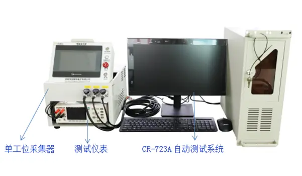
The Testing Section includes:
Hipot Testing
25°C Resistance Testing
85°C Resistance Testing
Data Capture
Automatic NG Separation
The planned testing capacity is approximately 2,000–4,000 wires/hour.
At this stage, the main task of the earlier fixture systems is largely complete.
The production interface starts to move away from the question of where the product is mechanically fixed and toward what measurement result the product produces under a defined test condition.
Robotlyne connects Resistance and High-Voltage Verification with database-backed data capture in the Testing Cell, followed by OK / NG handling based on the test result.
Across the complete project, the production interface changes four times:
Line Board
maintains Wire Preparation and Welding Position.
↓
Encapsulation Frame
reorganizes large quantities of Semi-Finished Sensors into batch units for Encapsulation and transfer.
↓
Potting Fixture
establishes a new assembly position for Shell Insertion and Dispensing.
↓
Testing Interface
converts the finished product into Resistance, Hipot, and OK / NG Data.
This is the role of the large number of Process Fixtures in Robotlyne’s NTC Sensor Automated Production Line. They act as the mechanical interfaces between different production stages.
The approximately 20,000-piece daily target is connected through these interfaces: front-end Boarding and Welding establish the initial product geometry, Encapsulation Frames organize the mid-process batch flow, Potting Fixtures support downstream Shell Assembly, and the Testing Section creates the performance record and NG result for the Finished Sensor.
For NTC Sensor projects that need to connect Wire Processing, Resistor Welding, Encapsulation, Shell Insertion, Dispensing, and Multi-Temperature Testing into one complete process, contact Robotlyne to plan the corresponding Automated Production Line around the actual Product Geometry, Daily Output, and Process Fixture Interfaces.