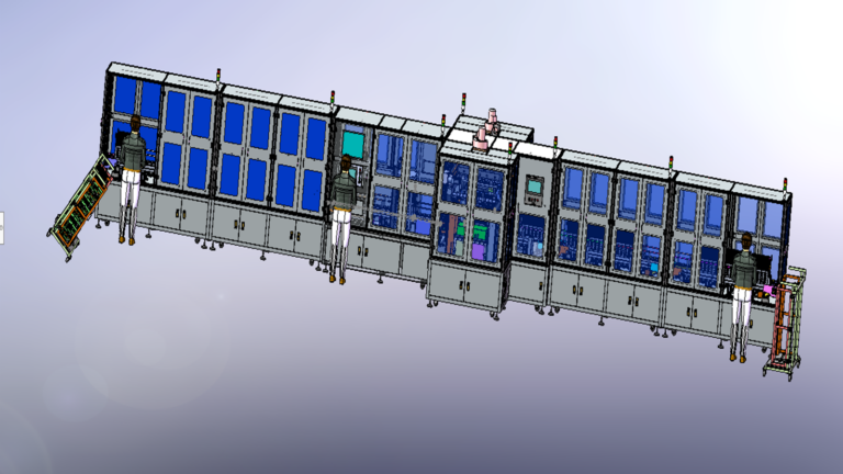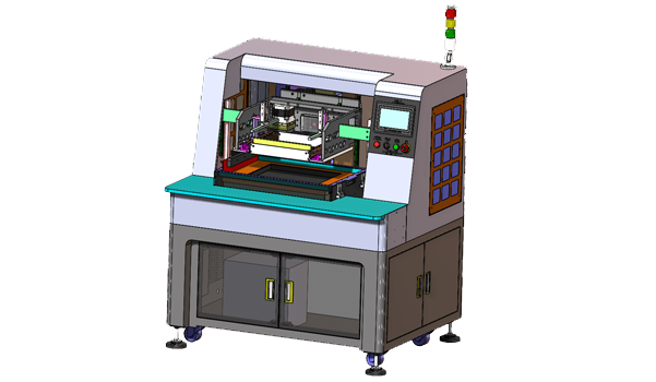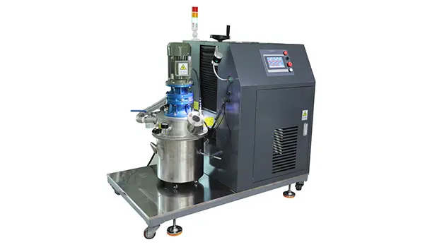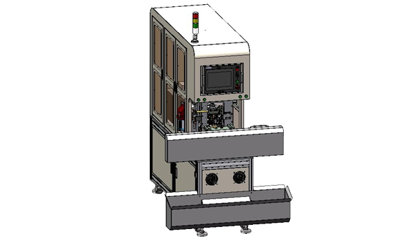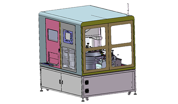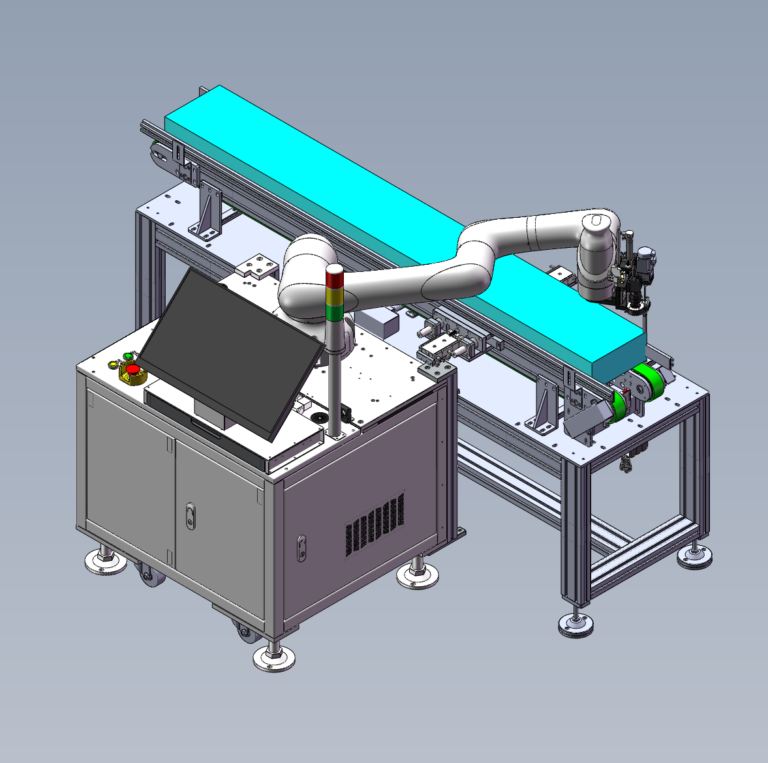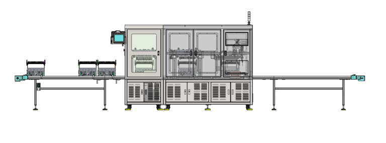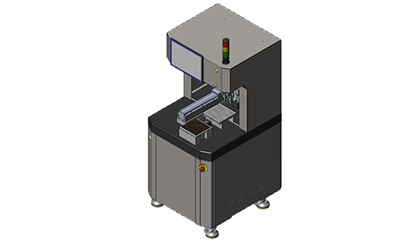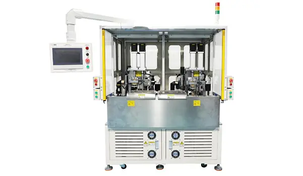
In Automotive sensor manufacturing, an Automotive NTC assembly line is shaped by more than the PCS/H rating of the Welding Machine. This Single-End Automotive NTC Line case is designed around a production target of approximately 8,000 pcs / 10-hour shift. The front end includes Automatic Cutting and Boarding and Single-End Welding, followed by Encapsulation, Baking, Shell Potting, Sealing-Ring Assembly, 25°C / 85°C Resistance Testing, and Data Collection. The project also specifies 120 Encapsulation Frames, 4 Turnover Carts, and 2 Floor-Push Ovens.
These machines and tooling resources carry different parts of the production load. Boarding and Welding can be described directly in PCS/H. Once the process moves into Encapsulation and Baking, products begin occupying Fixtures; those Fixtures travel with the products and remain engaged during the Oven Process. After these operations, the parts still have to enter two temperature-specific Resistance Testing conditions.
Capacity therefore moves through several different types of production resources as the product travels downstream.
Robotlyne’s NTC Sensor Production Automation covers Wire Processing, Welding, Dip Coating, Potting, Curing, and Testing, and is applicable to similar Automotive NTC production-line projects.
800 pcs/hour Is Only the Average Rate Required at the Front End
The project target is approximately:
8,000 pcs / 10-hour shift
Averaged across a 10-hour shift, this corresponds to approximately:
800 pcs/hour
The planned capacities of the two front-end sections are different:
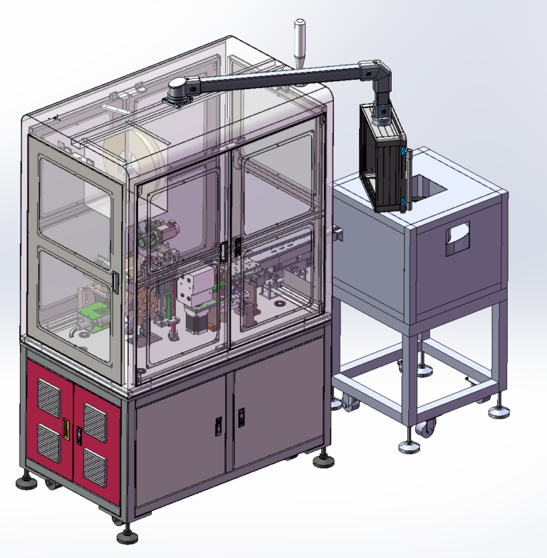
Cutting and Boarding: 1,800–2,000 pcs/hour
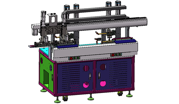
Single-End Dual-Machine Welding: 800–1,000 pcs/hour
The Boarding section has considerably more capacity than the average line-output requirement, allowing it to prepare products for downstream processing at a higher rate. Welding, by comparison, operates much closer to the average production rate the line needs to sustain.
If the product became a Finished Sensor immediately after Welding, the 800–1,000 pcs/hour figure would already describe much of the downstream production flow. In this line, however, Welding is followed by Encapsulation, Baking, Shell Potting, Sealing-Ring Assembly, and Temperature-Based Resistance Testing.
From this point onward, the production state begins to change.
Front end: Machine Processing Products
After Welding: Fixtures Carrying Products Through a Process
Every batch released from Welding needs available Encapsulation Frames before it can continue downstream. Fixture Availability therefore begins to participate directly in the production rhythm.
That is why the project defines 120 Encapsulation Frames, 4 Turnover Carts, and 2 Floor-Push Ovens as explicit production resources rather than treating them as peripheral tooling quantities.
Every Batch Leaving Welding Occupies Part of the Fixture Capacity
After Single-End Welding, the products move into Encapsulation.
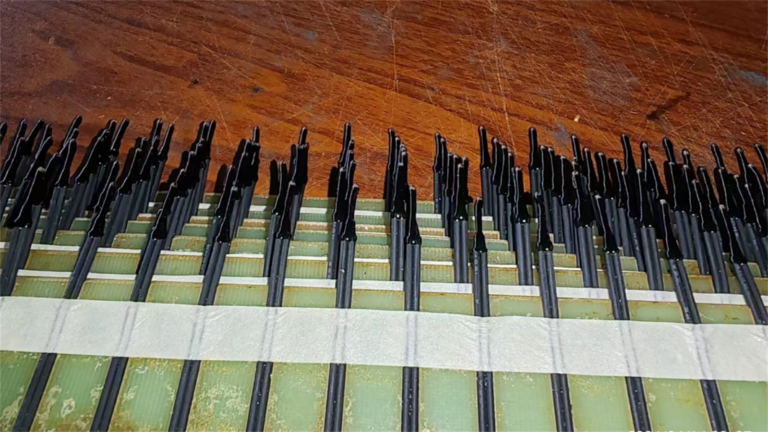
At this stage, a product no longer simply passes through one Machine and immediately leaves. It enters an Encapsulation Frame and continues through downstream processing together with the Fixture.
The production path can be viewed as:
Welding Output → Encapsulation Frame → Turnover → Baking → Fixture Return
As long as a Frame remains occupied by the current batch, that Fixture has not yet returned to the front of the process to receive the next batch.
For the approximately 8,000-piece-per-shift target, the project specifies:
120 Encapsulation Frames
4 Turnover Carts
2 Floor-Push Ovens
Each resource performs a different role. The Encapsulation Frame carries and holds the products. The Turnover Cart moves Fixtures and Products between process areas. The Floor-Push Oven handles the Baking stage, during which part of the Frame population remains occupied together with the products being processed.
The workshop therefore operates through a repeating cycle. Welding completes a batch, available Frames receive the products, the Frames move through Encapsulation and Baking, other available Frames continue receiving new Welding Output, and Frames that finish the current process return to production for the next batch.
The Welding Section’s 800–1,000 pcs/hour describes how quickly products can be released downstream. The 120 Frames, 4 Carts, and 2 Ovens describe another form of production capacity: how many products can be held in downstream processing at the same time and how those Fixtures continue circulating.
Even when Welding still has available Machine Capacity, the number of Fixtures immediately available for new batches falls when many Frames are simultaneously in Baking or intermediate turnover. Adding more Frames alone does not isolate the issue, because those Fixtures still have to move through Cart Transfer and the Oven Process.
The complete system depends on a continuous circulation:
Welding continuously releases products
Frames are continuously occupied
Carts continuously move Fixtures
Ovens continuously release baked products and Frames
Frames return to production
This is a different way of expressing capacity from the PCS/H rating of a single Welding Machine.
After the Oven, the Product Still Enters 25°C and 85°C Test Flow
After Encapsulation and Baking, the products continue through Shell Potting, Sealing-Ring Assembly, and Resistance Testing.
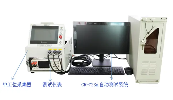
The Testing Section includes:
25°C Resistance Testing
85°C Resistance Testing
and is connected to Data Collection. The project uses Manual Loading with Automated Collection and also includes an Optional Semi-Automatic Tester configuration.
At this stage, the production flow changes again.
Front end: Product → Machine
Encapsulation and Baking: Product → Fixture → Cart → Oven
Testing: Product → Test Condition → Resistance Data
The 25°C and 85°C tests represent two defined temperature conditions. After mechanical assembly and material processing are complete, the product still has to enter the corresponding Test Environment for Resistance Measurement and Data Collection.
Finished Welding and Baking output therefore continues into a downstream Test Flow that must keep receiving products. In this project, Manual Loading is retained in the Testing Section, while automation is concentrated on Measurement and Data Collection.
The complete Automotive NTC assembly line forms a clear capacity path:
8,000 pcs / 10-hour shift
↓
Cutting & Boarding — 1,800–2,000 pcs/hour
↓
Welding — 800–1,000 pcs/hour
↓
120 Encapsulation Frames
↓
4 Turnover Carts
↓
2 Floor-Push Ovens
↓
25°C / 85°C Resistance Testing
↓
Data Collection
From the front end to the back end, the resource controlling production capacity keeps changing. Boarding determines the product-preparation rate. Welding determines the downstream release rate. Frames determine how many products can enter post-processing at the same time. Carts maintain Fixture movement between production areas. Ovens handle Baking. The 25°C / 85°C tests then convert assembled and processed parts into Finished Sensors with Resistance Data.
In this Automotive NTC assembly line, 120 Frames, 4 Carts, and 2 Ovens belong to the same capacity system as the 800–1,000 pcs/hour Welding Capacity. Together, they influence whether the approximately 8,000 pcs / shift production target can be sustained rather than operating as isolated peripheral items on an equipment list.
If an Automotive NTC production process also needs to connect Welding, Encapsulation, Baking, Fixture Turnover, and multi-temperature testing, contact Robotlyne to plan the NTC production line around Daily Output, Fixture Circulation, Oven Process, and Testing Flow.